Display and display drive circuit or display drive method

A display device and circuit technology, applied to static indicators, cathode ray tube indicators, instruments, etc., can solve the problems of longer signal lines, larger signal reflection distortion, and signal degradation

Inactive Publication Date: 2006-03-22
NICHIA CORP
View PDF6 Cites 0 Cited by
  • Summary
  • Abstract
  • Description
  • Claims
  • Application Information

AI Technical Summary

Problems solved by technology

Therefore, the driver IC on the right end must be connected to the driver IC on the left end, and the signal line becomes longer, so there is a disadvantage that the wiring becomes complicated
Furthermore, since the signal line is extended, the reflection distortion of the signal between the terminals increases, causing problems such as signal degradation and noise caused by wrapping.

Method used


Image

  • Display and display drive circuit or display drive method
  • Display and display drive circuit or display drive method
  • Display and display drive circuit or display drive method

Examples


Embodiment

[0120] Examples of the invention of the present application will be described below, but the invention of the present application is not limited to the following examples.

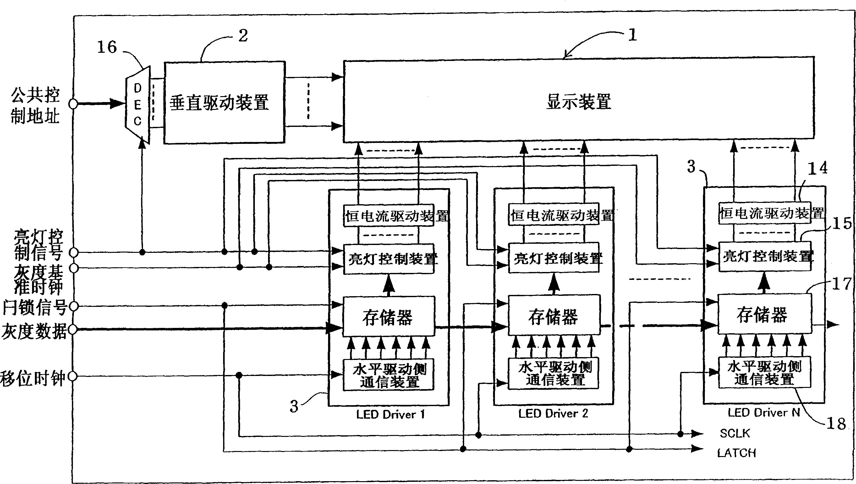
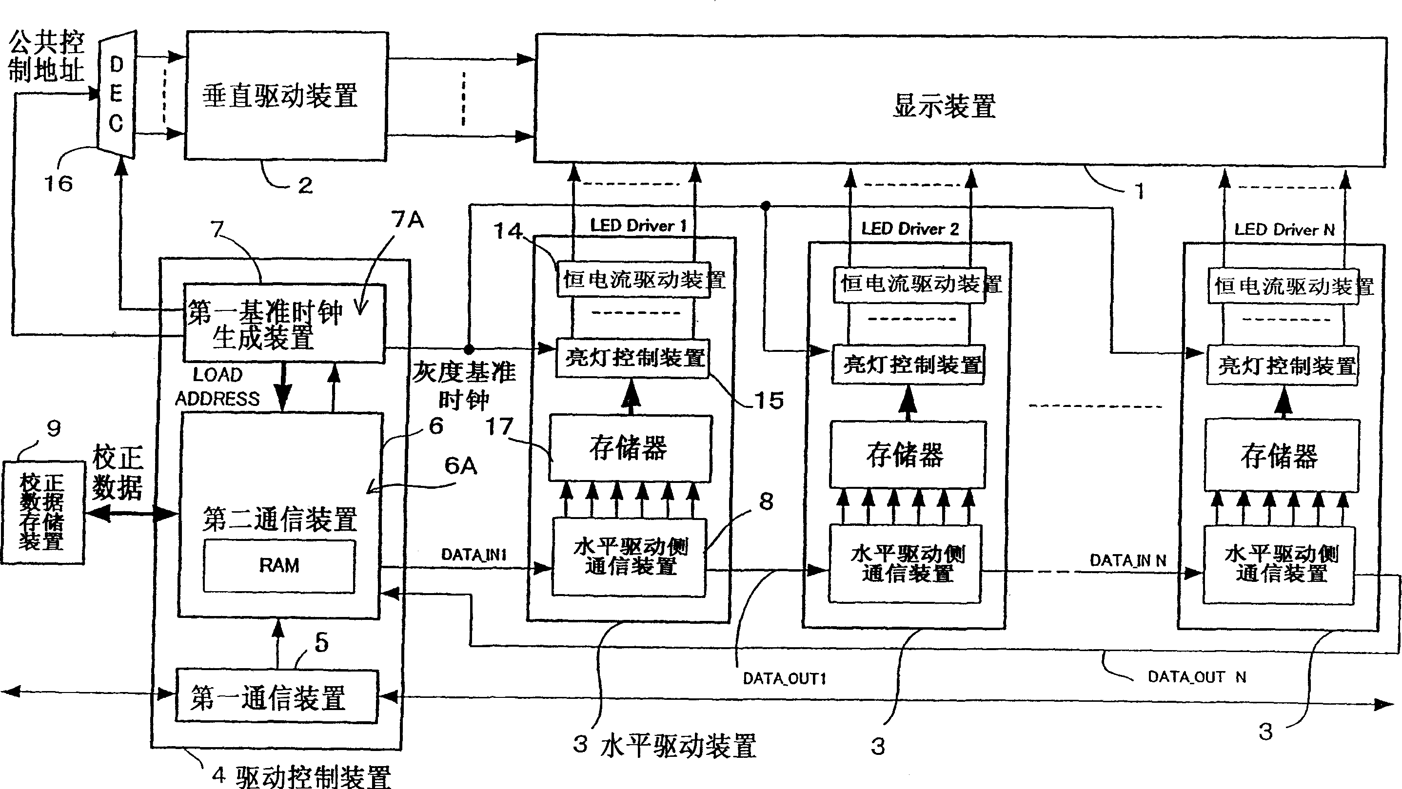
[0121] figure 2 It is a block diagram schematically showing an example of a display device according to the present invention. The display unit shown in this figure consists of:

[0122] (a) a display device 1 in which a plurality of light emitting elements 11 are arranged in a matrix of m rows×n columns;

[0123] (b) a vertical drive device 2 for applying a current to each row of the display device 1 while selecting the row;

[0124] (c) a horizontal driving device 3 for supplying a driving current to each column of the display device 1 according to the image data corresponding to the selected row;

[0125] (d) drive control device 4 provided with first communication device 5, second communication device 6, first reference clock generation device 7;

[0126] (c) Correction data storage means 9 storin...


PUM


Abstract

A display comprises horizontal drive units (3) and a drive control unit (4) for controlling the horizontal drive units (3) all having a data communication function. The drive control circuit (4) comprises a first communication section (5) for receiving data from outside and a second communication section (6) for communicating data with the horizontal drive units (3). The second communication section (6) adds identification information (23) for identifying the horizontal drive units (3) to transmission data and transmits the data in the form of a packet. Each of the horizontal drive units (3) receives the corresponding data packet (20) according to the identification information (23) and carries out current drive of a display unit (1). The drive control unit (4) adds identification information (23) to control data to be transmitted to the horizontal drive units (3) depending on the connection status of the horizontal drive units (3) and transmits control data irrespective of the connection order of the horizontal drive units (3). The horizontal drive units (3) receive the data packets and drive the display.

Description

technical field [0001] The present invention relates to a display device, a display driving circuit, and a display driving method in which a plurality of light emitting elements are arranged in a matrix as required. Lighting data such as lighting data and lighting data are sent to multi-stage connected drive circuits in the form of predetermined data, and various corrections such as gradation, brightness, and characteristics are performed. Background technique [0002] This application is a priority application based on Japanese Patent Application No. 2000-230095 and Japanese Patent Application No. 2000-230624. [0003] Recently, high-intensity light-emitting elements such as light-emitting diodes (Light Emitting Diode, hereinafter referred to as "LED") have been developed for RGB, which is the three primary colors of light. A large self-illuminating full-color display was manufactured. In addition, products and the like have been developed as various types of lighting suc...

Claims


Application Information

Patent Timeline
Patent Type & Authority Patents(China)
IPC IPC(8): G09G3/32G09G3/20G09G5/18
CPCG09G3/32G09G3/2014G09G3/2018G09G5/18G09G2300/026G09G2310/0221G09G2310/0275G09G2310/0297G09G2320/0276G09G2330/08G09G3/20
Inventor 永井芳文辻隆平
Owner NICHIA CORP
Why Eureka
Try Eureka