Switching device comprising switch lock

A switch device and switch lock technology, which is applied to the parts of protection switches, protection switches, emergency protection devices, etc., can solve problems such as adverse effects and achieve the effect of reducing costs

Inactive Publication Date: 2006-03-29
SIEMENS AG
View PDF3 Cites 0 Cited by
  • Summary
  • Abstract
  • Description
  • Claims
  • Application Information

AI Technical Summary

Problems solved by technology

However, the above-mentioned prior art line protection switches have a structure that adversely affects this parameter

Method used


Image

  • Switching device comprising switch lock
  • Switching device comprising switch lock
  • Switching device comprising switch lock

Examples


Embodiment Construction

[0020] In the following description, the same components in the respective drawings are denoted by the same reference numerals or components having the same meaning are denoted by similar reference numerals.

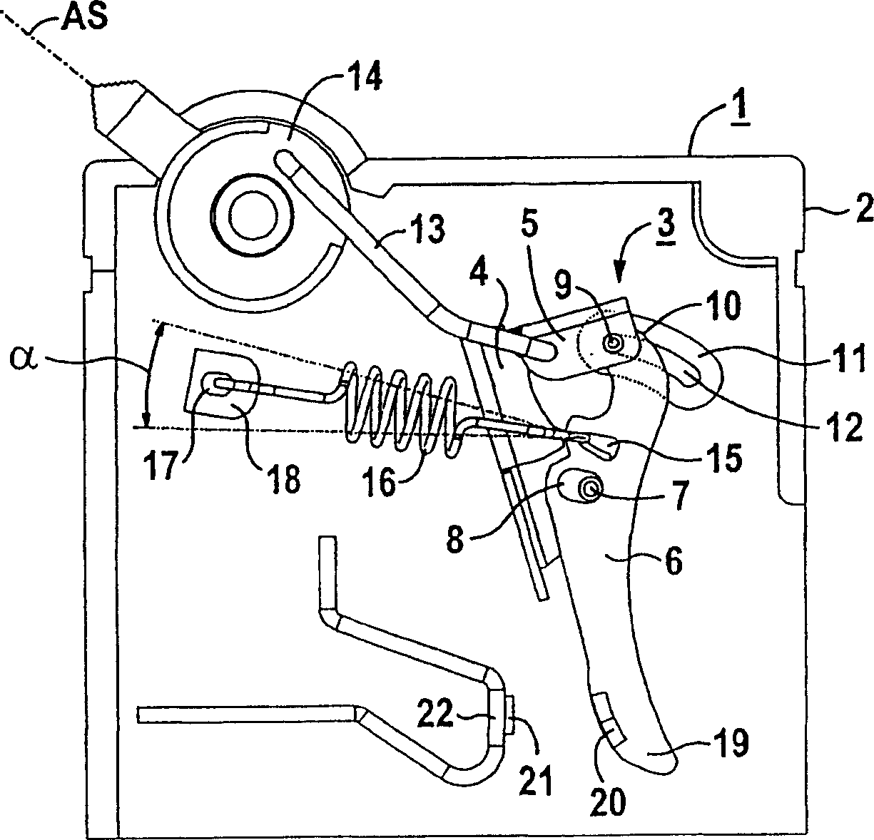
[0021] figure 1 A switching device 1 with a housing 2 and a switch lock 3 is shown in the so-called disconnected position AS. The switch lock 3 has a trip lever 4, a pawl 5, a movable contact arm 6 and a rotary shaft 7 fixed on the housing. In this view, the contact arm 6 has an approximately mirror-inverted S-shape and approximately centrally over its component length, in particular with a length ratio of 1:2, there is provided a shaft for accommodating the pivot axis therein. 7 grooves 8.

[0022] The groove 8 can be designed as open or closed and points substantially in the direction of the trip lever 4 over the component width of the contact arm 6 . With respect to the rotary shaft 7, the groove 8 has an interference dimension, thereby achieving the purpose of con...


PUM


Abstract

A switching device including housing and a breaker mechanism, the latter consisting of a trip lever, a catch, a displaceable contact arm and a deflection shaft that is fixed to the housing. The aim is to generate a constant contact force. To achieve this, the end of the catch is coupled to the displaceable contact arm by way of a bolt. The bolt is configured to be displaced in a receiving element that is formed by the housing.

Description

technical field [0001] The invention relates to a switching device with a housing and a switch lock with a release lever, a pawl, a movable contact arm and a pivot shaft fixed to the housing. The movable contact arm is provided with a recess in which the pivot shaft is seated, and wherein the pawl is coupled with the movable contact arm at the end of the pawl by means of a pin. Background technique [0002] A switching device with a switch lock, in particular a protective switching device, can be used, for example, as a circuit breaker. Currently, line protection switches (also known as LS switches or line protection automatics) are mainly used instead of fuse protection devices. Line protection switches are overcurrent protection switches having a first and a second trip mechanism acting on a switch lock. An electromagnetic trip unit is used to quickly open the circuit in the event of a short circuit. A bimetallic thermal release is used to disconnect the circuit in the ...

Claims


Application Information

Patent Timeline
Patent Type & Authority Patents(China)
IPC IPC(8): H01H71/52
CPCH01H71/526H01H2071/0292
Inventor 温弗里德·维尔林
Owner SIEMENS AG
Why Eureka
Try Eureka