Unlock instant, AI-driven research and patent intelligence for your innovation.

Display drive, electrooptical device and parameter setting method of display drive

A technology for displaying drivers and correcting parameters, which can be applied to static indicators, instruments, etc., and can solve problems such as differences in display characteristics

Inactive Publication Date: 2006-04-19
SEIKO EPSON CORP
View PDF0 Cites 0 Cited by
  • Summary
  • Abstract
  • Description
  • Claims
  • Application Information

AI Technical Summary

Problems solved by technology

[0003] However, since there is a difference in display characteristics in the display panel of a liquid crystal device, how to suppress the influence of the difference has become an important technical issue.

Method used


Image

  • Display drive, electrooptical device and parameter setting method of display drive
  • Display drive, electrooptical device and parameter setting method of display drive
  • Display drive, electrooptical device and parameter setting method of display drive

Examples


Embodiment Construction

[0037] Embodiments to which the present invention is applied will be described in detail below using the drawings. In addition, the embodiments described below do not unduly limit the contents of the present invention described in the claims. All the configurations described below are not essential configuration requirements of the present invention.

[0038] 1. Electro-optical device

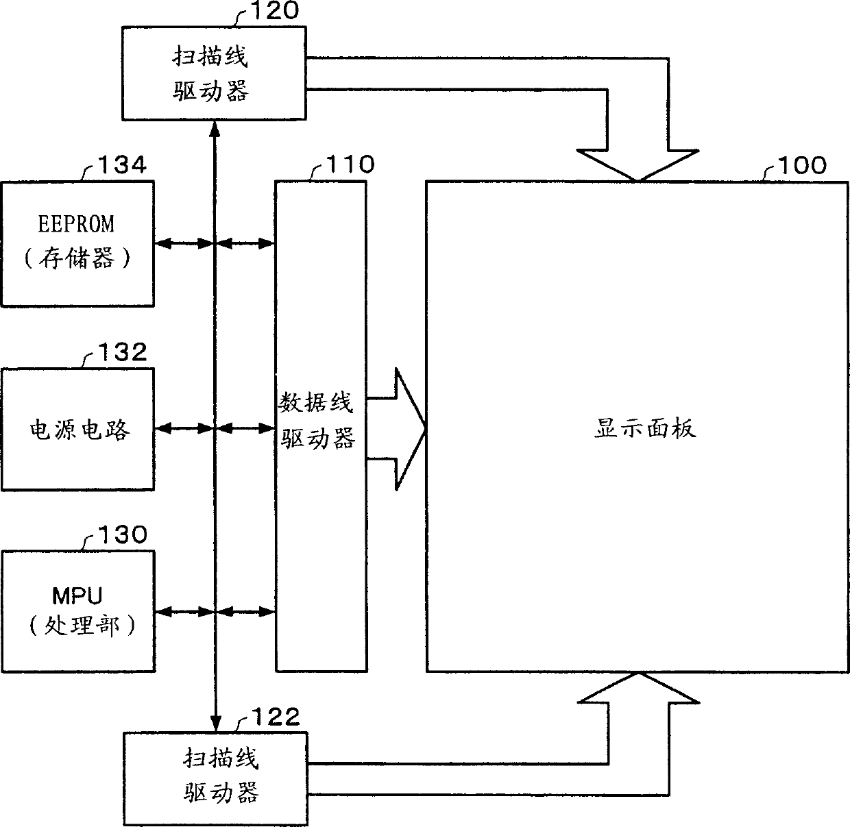
[0039] FIG. 1 shows a configuration example of an electro-optical device according to this embodiment.

[0040] This electro-optical device (a liquid crystal device in a narrow sense) includes a display panel 100 (a liquid crystal panel in a narrow sense).

[0041] The display panel 100 has a plurality of data lines (signal lines); a plurality of scan lines; and a plurality of pixels specified by the data lines and the scan lines. In this way, the display operation is realized by changing the optical characteristics of the electro-optical elements (liquid crystal elements in the narrow sense...


PUM


Abstract

A display driver includes a correction parameter register 40 which stores correction parameters for correcting contrast adjustment values; a computation circuit 50 which adds a correction value specified by a correction parameter to a contrast adjustment value instructed by an MPU, to calculate a corrected contrast adjustment value; and a drive circuit which drives a display panel with a drive voltage that is obtained based on the corrected contrast adjustment value. The display driver uses a correction value for a contrast reference value that is obtained by measuring a display characteristic of the display panel. At power-on, at a system reset, or at refresh timing, a correction parameter that has been read from the EEPROM is written to the correction parameter register, to initialize or refresh the register.

Description

technical field [0001] The invention relates to a display driver, an electro-optical device and a parameter setting method of the display driver. Background technique [0002] In liquid crystal devices (electro-optical devices in a broad sense) used in electronic equipment such as mobile phones, it is desired to perform display operations with optimum display characteristics (contrast). [0003] However, since there are differences in display characteristics among the display panels of liquid crystal devices, how to suppress the influence of the differences has become an important technical issue. [0004] In addition, it is desired that the display characteristics of the liquid crystal device be maintained in an optimum state even when external causes such as static electricity (ESD) occur. [0005] Furthermore, in electronic equipment incorporating a liquid crystal device, the firmware of the electronic equipment controls the display operation of the liquid crystal device...

Claims


Application Information

Patent Timeline
Patent Type & Authority Patents(China)
IPC IPC(8): G09G3/00G02F1/133G09G3/20G09G3/36
CPCG09G3/20G09G2320/066
Inventor 田村刚
Owner SEIKO EPSON CORP