
Electric shaver

A technology of electric razors and razors, which is applied in metal processing and other directions, can solve the problems of increased overall weight, and achieve the effect of reducing production costs and reducing costs

Inactive Publication Date: 2006-08-30
KYUSHU HITACHI MAXELL LTD
View PDF2 Cites 0 Cited by
  • Summary
  • Abstract
  • Description
  • Claims
  • Application Information

AI Technical Summary

Problems solved by technology

However, although the power transmission mechanism can be simplified at this time, the size of the motor itself is inevitably increased, and the size of the electric shaver is unavoidable. Although the power transmission mechanism is simplified, the overall weight increases.

Method used


Image

  • Electric shaver
  • Electric shaver
  • Electric shaver

Examples


Embodiment Construction

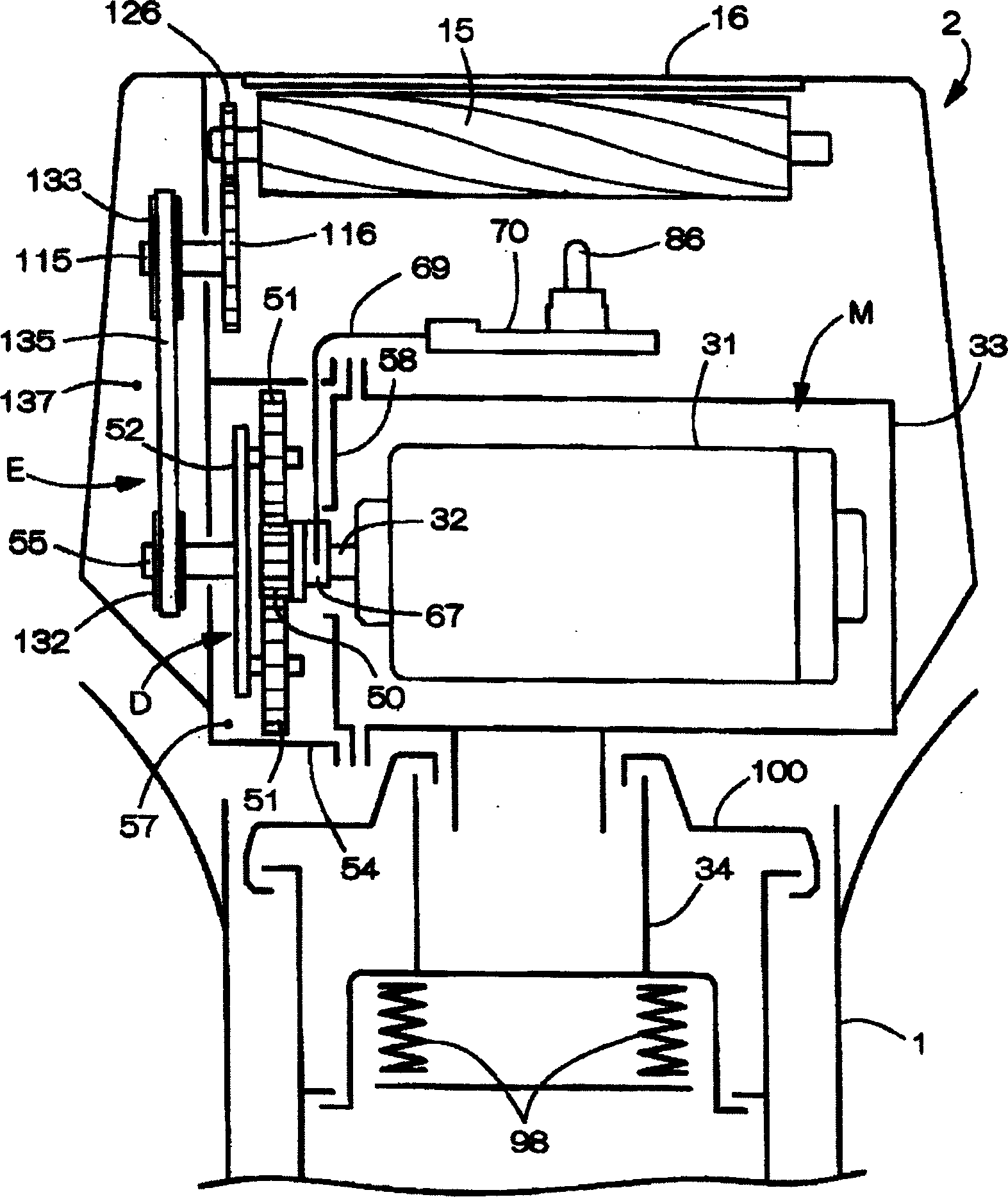
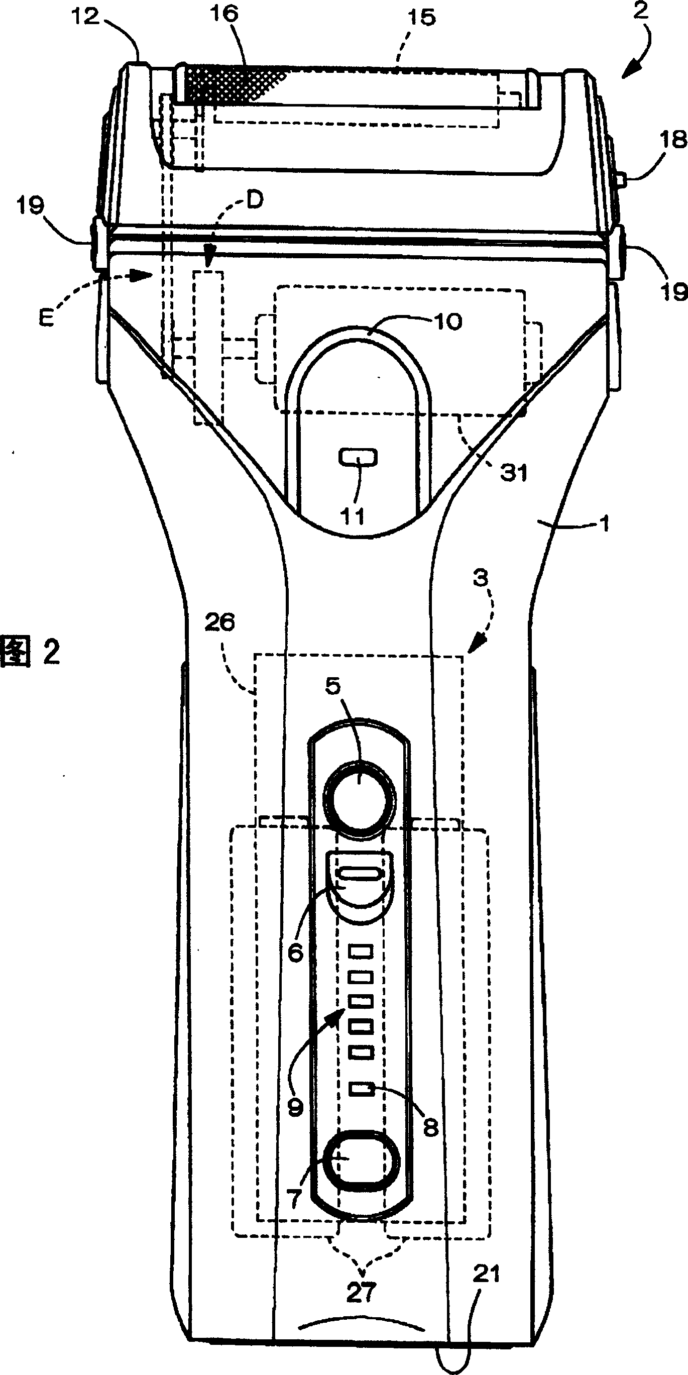
[0077] Figure 1 to Figure 3 A vote of 0 indicates an embodiment in which the present invention is applied to a rotor type electric shaver. The structure of the electric shaver among Fig. 2 to Fig. 4 is to have the main structural components such as the main casing 1, the shaver head 2 that is arranged on the top of the main casing 1, and the electrical device unit 3 accommodated in the main casing 1.

[0078] In the front of the main casing 1, there are switching operation components such as a switch button 5 for starting the motor, a locking button 6, a selection button 7 for switching operation modes, and the like; and a display component. The display part includes four kinds of lights: the charging light 8 on the upper side of the selection button 7, the remaining battery level display light 9, the inverted U-shaped mode display light 10 on the upper part of the casing that can change color corresponding to the operating mode and The sensor lamp 11 which lights up in conjun...


PUM


Abstract

The motor 31 is made into one body with a deceleration transmission mechanism D for decelerating motor power, so as to obtain one power module M. Thus, the structure of the power transmission mechanism from the motor 31 to the cutter 15 is simplified simultaneously with raising transmission efficiency. The unitized power module M is utilized as a power source for the different kinds of electric razors. Power decelerated by the deceleration transmission mechanism D is transmitted to the cutter 15 via a succeeding stage transmission mechanism E. The deceleration transmission mechanism D includes a planet gear mechanism, so as to obtain a prescribed deceleration ratio, while minimizing the engagement part of gears, to suppress the generation of gear noise. The succeeding stage transmission mechanism E includes a wrapping transmission mechanism with an endless belt 135 as a transmission element. The noise, therefor, is prevented from being generated in the succeeding stage transmission mechanism E, and a noise level is lowered in the outer part of the electric razor.

Description

technical field [0001] The present invention relates to an electric shaver with an improved power transmission mechanism including a speed reduction mechanism from a motor to a cutting blade. Background technique [0002] Regarding the rotor-type electric shaver, Japanese Patent No. 2741054 (hereinafter referred to as Patent Document 1) discloses the following content: the vertically arranged motor and the inner blade unit equipped with a power transmission mechanism are integrated, in other words, the motor and Unitization of power transmission mechanism (see page 2 and figure 1 ). In this invention, though a flexible transmission mechanism is used to form part of the power transmission mechanism from the motor to the cutting blade to reduce transmission noise, the power transmission mechanism used is known, see Japanese Patent Laid-Open Publication 2002- No. 306864 (hereinafter referred to as Patent Document 2), however, the electric shaver wherein is not configured with...

Claims


Application Information

Patent Timeline
Patent Type & Authority Patents(China)
IPC IPC(8): B26B19/14B26B19/28B26B19/32
CPCB26B19/146B26B19/28B26B19/3853
Inventor 山下康雄泰藤义典冈本祐介规工川健作
Owner KYUSHU HITACHI MAXELL LTD
Learn More