Motor for vacuum cleaner

A technology for vacuum cleaners and motor casings, applied to electrical components, electromechanical devices, etc., can solve problems such as poor contact, deformation of brush terminals 32, failure to start the motor, etc., and achieve the effect of improving product reliability

Inactive Publication Date: 2006-10-04
LG ELECTRONICS (TIANJIN) APPLIANCES CO LTD
View PDF0 Cites 0 Cited by
  • Summary
  • Abstract
  • Description
  • Claims
  • Application Information

AI Technical Summary

Problems solved by technology

[0005] like Figure 2a and Figure 2b The shown prior art vacuum cleaner motor has the disadvantage that when the brush 31 is inserted from the outside to the inside of the motor housing 110, the free end portion of the stator terminal 14 is excessively pushed toward the bent portion 32a of the brush terminal 32, cause the brush terminal 32 to deform
Therefore, poor contact between the stator terminal 14 and the brush terminal 32 occurs, and the motor cannot be started.

Method used


Image

  • Motor for vacuum cleaner
  • Motor for vacuum cleaner
  • Motor for vacuum cleaner

Examples


Embodiment Construction

[0026] Referring to the accompanying drawings, a motor for a vacuum cleaner according to an example of the present invention will be described in detail.

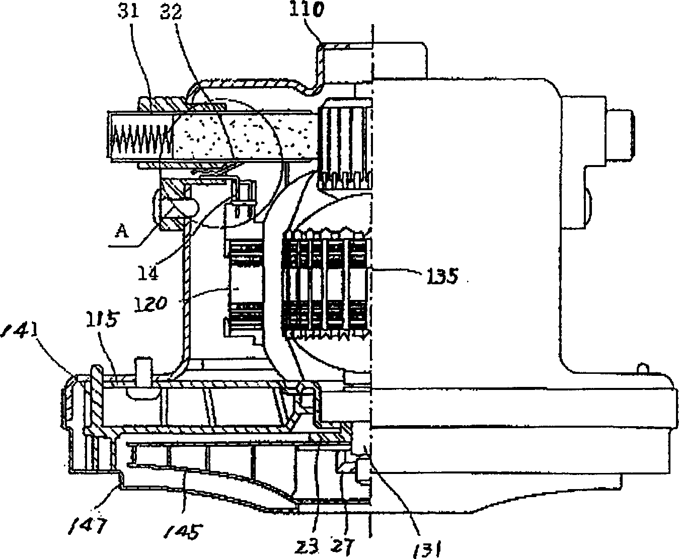
[0027] image 3 It is a simple structural diagram of a motor for a vacuum cleaner according to an example of the present invention.

[0028] As shown, the motor 100 has an open motor housing 110 underneath. The stator 120 is pressed and fixed inside the motor housing 110 . Inside the stator 120, there is a rotor 135 pressed into the motor shaft 131 so as to be rotatable. The motor cover 115 covering the lower part of the rotor 135 is integrally connected with the motor casing. Guide vanes 141 are provided on the motor cover 115 . An impeller 145 is fixed to an end portion of the shaft 131 protruding from the outside of the guide vane 141 . An impeller cover 147 surrounding the impeller 145 is fixed on the motor housing 110 . The brush 150 is inserted from the outside to the inside of the motor casing 110 and installed...


PUM


Abstract

A motor for vacuum cleaner is composed of casing, end covers, stator, rotor, shaft, blade wheel and its cover, stator terminal, and electric brush and its terminals for contacting with stator terminal. Its feature is that said electric brush has 3 contact parts with stator terminal, so having high contact reliability.

Description

technical field [0001] The invention belongs to motors, in particular to motors for vacuum cleaners. Background technique [0002] Refer below figure 1 , Figure 2a and Figure 2b , a prior art motor for a vacuum cleaner will be described. figure 1 It is a simple structural diagram of a motor for a vacuum cleaner in the prior art, Figure 2a and Figure 2b is during the contact between the stator terminals and the brush terminals figure 1 Enlarged view of part "A", Figure 2a When the brush 31 is inserted from the outer surface of the motor case 110 inward, the stator terminal 14 just contacts the brush terminal 32, Figure 2b This is the case when the brush 31 is fully inserted. [0003] Such as figure 1 As shown, on the inner side of the motor housing 110, the stator 120 with the stator terminal 14 is forcibly installed, and the rotor 135 is pressed into the rotor 135 with the motor shaft 131, and the rotor 135 is located inside the stator 120. The motor cover 11...

Claims


Application Information

Patent Timeline
Patent Type & Authority Patents(China)
IPC IPC(8): H02K13/00
Inventor 朴柱洪
Owner LG ELECTRONICS (TIANJIN) APPLIANCES CO LTD
Why Eureka
Try Eureka