Eureka AIR delivers breakthrough ideas for toughest innovation challenges, trusted by R&D personnel around the world.

Electric punching device

A hole puncher, electric technology, applied in metal processing and other directions, can solve the problems of large size, difficult to carry, a large number of disassembly, etc., to achieve the effect of light weight

Inactive Publication Date: 2006-11-08
KTF
View PDF1 Cites 0 Cited by
  • Summary
  • Abstract
  • Description
  • Claims
  • Application Information

AI Technical Summary

Problems solved by technology

[0004] A disadvantage of this traditional electric hole punch is its large size and therefore relatively heavy and difficult to carry
Another disadvantage is that although the distance between the two punched holes can be set at 70 mm or 80 mm, a spacer (separation element) needs to be installed on the shaft for width adjustment, which causes a lot of disassembly

Method used


Image

  • Electric punching device
  • Electric punching device
  • Electric punching device

Examples


Embodiment Construction

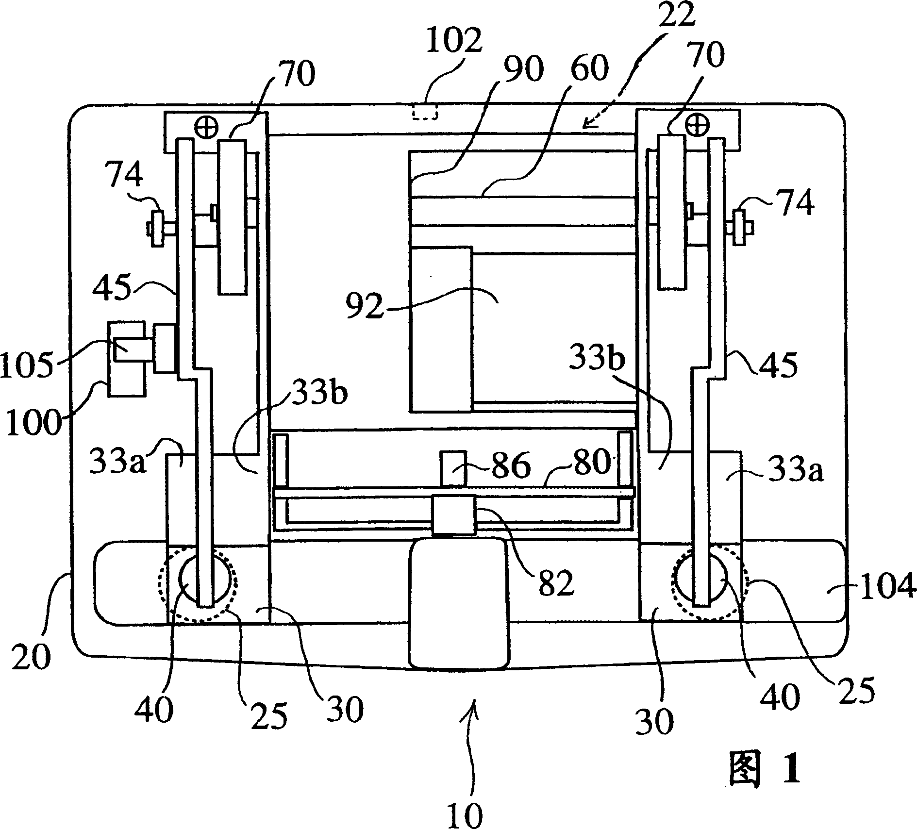
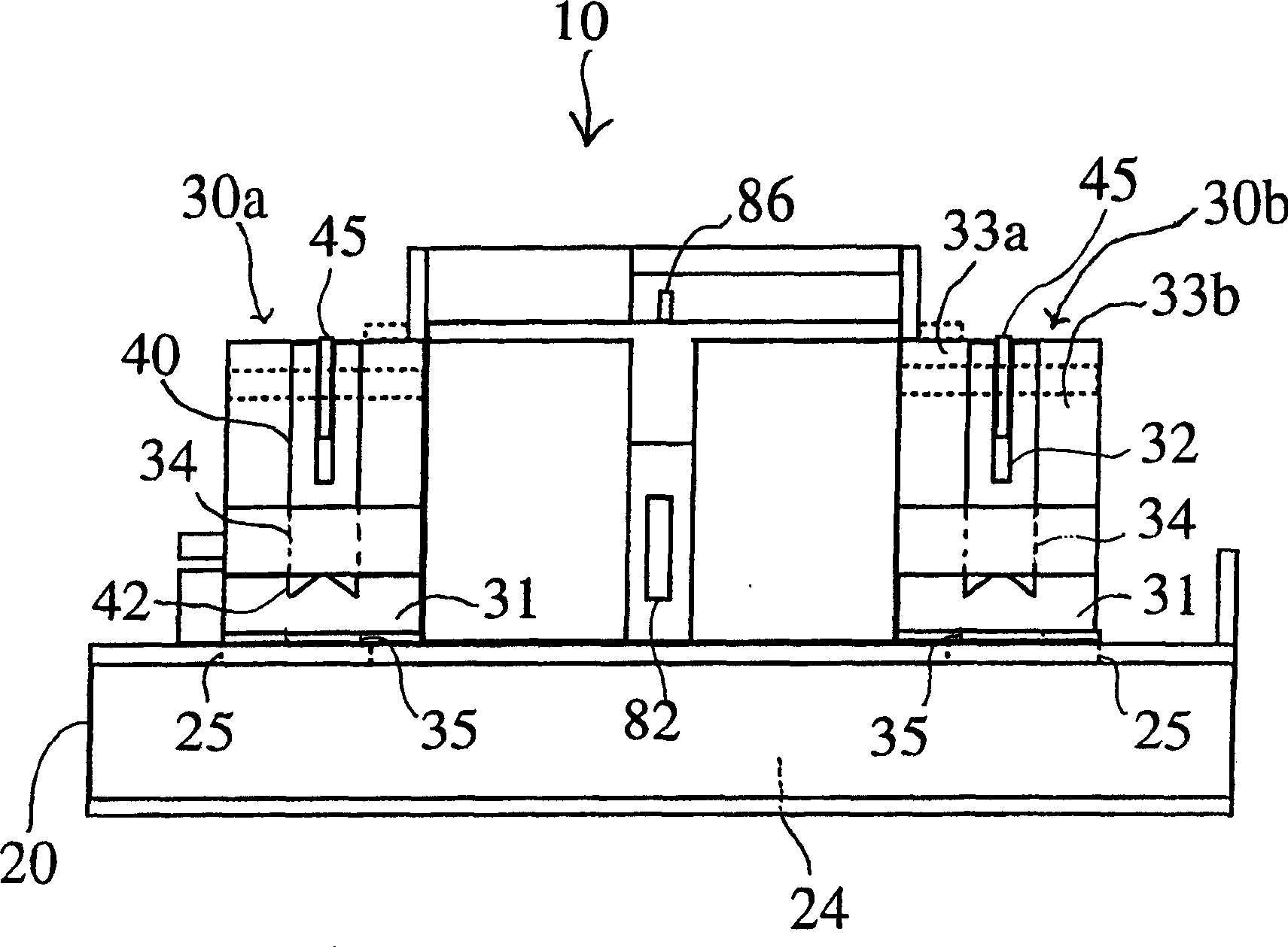
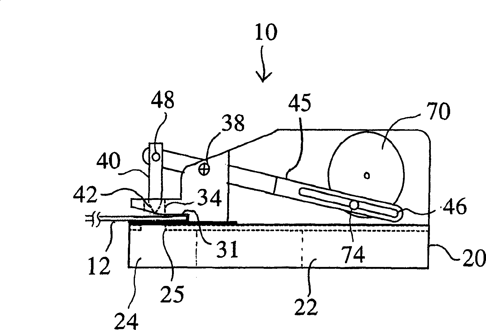
[0021] An embodiment of the electric hole puncher of the present invention will now be described with reference to the accompanying drawings. Figures 1, 2 and 3 are the plan view, front view and side view of the electric puncher with the hole pitch set at 70 mm, respectively. Fig. 4 is a plan view of an electric puncher with a pitch of 80 mm.

[0022] Figure 1 and figure 2 As shown, the electric hole puncher 10 according to the present invention includes a main frame 20 , a supporting member 30 , a punching member 40 and a driving part 90 .

[0023] The main frame 20 is composed of a battery case 22 , a paper waste collection tank 24 and a drive section 90 including a motor 92 . The battery box 22 is a shell for loading one or more batteries as a power source, and also has an openable box cover.

[0024] The paper dust collection tank 24 is a housing for collecting paper dust generated when documents and the like are punched, that is, paper dust from a stack of paper 12 ( ...


PUM


Abstract

Disclosed is an electric hole puncher capable of automatically punching holes in documents and the like. By forming intermediate bends on the length of the operating arms of each punching piece, the front and rear sections of the operating arms are laterally offset in parallel. The specified distance is used, and the operating arm is clamped by two supporting pieces of different widths, so the hole distance can be changed by exchanging the left and right punching pieces, and the distance between the two holes can be set at 70 mm ( American standard) or 80mm (European and Japanese standard).

Description

field of invention [0001] The present invention relates to an electric hole puncher for punching holes in archived documents and other sheet materials, and more particularly to an electric hole puncher in which the pitch of the holes can be selected at 70° only by changing the positions of the components. mm or 80 mm. Background technique [0002] Hole punches are commonly used as hole forming devices for forming holes in filed documents and other sheet materials. There are two kinds of punchers, manual and electric (electricity is used as power), commonly used. While manual hole punches are commonly used, they require a lot of effort when punching thick stacks of paper and crease the middle of the top page to mark the binding of each stack orientation center. Electric hole punches are convenient because they can be driven automatically by electricity. A typical electric hole puncher is as described in Japanese Patent No.1967332. [0003] The electric hole puncher discl...

Claims


Application Information

Patent Timeline
IPC IPC(8): B26F1/00B26F1/34B26F1/14B26D7/26
CPCB26D7/2628B26F1/34Y10T83/885Y10T83/9423Y10T83/9442Y10T83/9464Y10T83/8831
Inventor 星野浩康
Owner KTF
Why Eureka
Eureka Blog
Learn More