Ferroelectric liquid crystal display, and its driving method

A technology of ferroelectric liquid crystals and display elements, applied in static indicators, instruments, nonlinear optics, etc., can solve problems such as insufficient prevention of image persistence and image persistence, and achieve reduced display flicker, good display, Effect of preventing threshold voltage change

Inactive Publication Date: 2001-03-14
CITIZEN WATCH CO LTD
View PDF0 Cites 3 Cited by
  • Summary
  • Abstract
  • Description
  • Claims
  • Application Information

AI Technical Summary

Problems solved by technology

However, the present inventors have found that one of the causes of image persistence is a change in the threshold voltage required to produce the transition from the first steady state to the second steady state, and the phenomenon of image persistence can occur in a very short time
It was also found that t

Method used


Image

  • Ferroelectric liquid crystal display, and its driving method
  • Ferroelectric liquid crystal display, and its driving method
  • Ferroelectric liquid crystal display, and its driving method

Examples


Embodiment 1

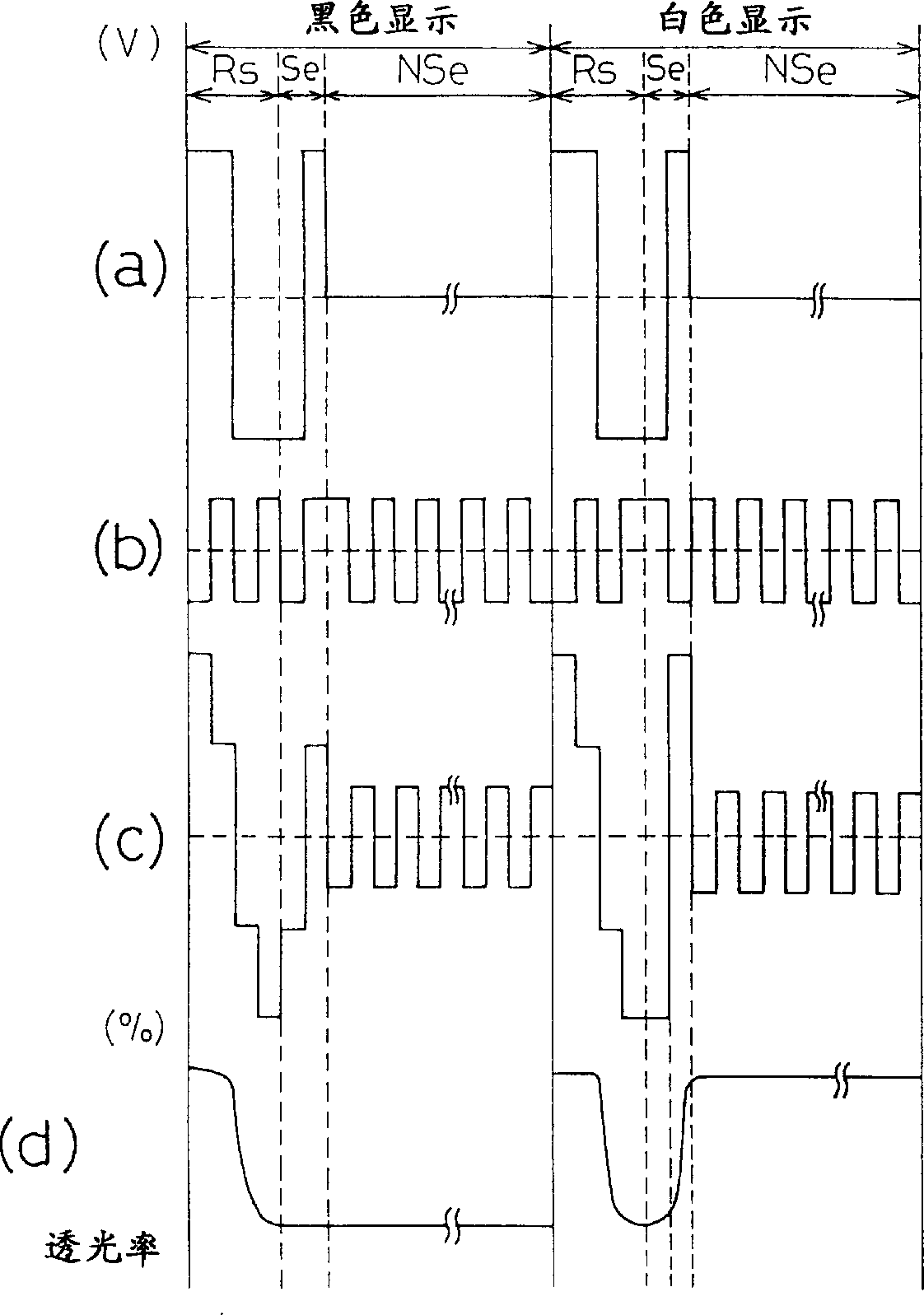
[0059] Figure 11 is a schematic diagram showing a method of synthesizing driving voltages according to the first embodiment of the present invention. This way corresponds to image 3 (c) Synthetic voltage driving method shown.

[0060] N=1 indicates the composite voltage mode applied to the pixels on the scan electrodes of the first row, N=2 indicates the composite voltage mode applied to the pixels on the scan electrodes of the second row, and N=240 indicates the composite voltage mode applied to the 240th row Synthetic voltage mode of the pixel on the scan electrode. In the present invention, all pixels are simultaneously placed in the black display state in the reset period (Rs) immediately before the selection period (Se) in which the necessary display data is written, and then each scan electrode is sequentially Writing is completed by applying a selection pulse. As shown in Figure 6, the reset period (Rs) is divided into two periods, the switching period (Sw) and th...

Embodiment 2

[0065] Figure 13 is a schematic diagram showing a method of synthesizing driving voltages according to the second embodiment of the present invention. In this embodiment, a reset period (Rs) is provided every time display data is written to a pixel. For each scanning line, the reset period is set such that the lengths of the switching period (Sw) and the non-switching period (NSw) are the same for all pixels. The length of the reset period (Rs) of each pixel is set to 8.2 ms, and the lengths of the switching period (Sw) and the non-switching period (NSw) are set to about 8 ms. The bipolar pulse applied during the switching period (Sw) and the selection pulse applied during the selection period (Se) are the same as in the first embodiment. As a result, the change amount of the threshold voltage is the same for all scanning lines, and better display quality can be achieved.

[0066] In this embodiment, a black display is generated during the reset period, of course, the same...


PUM


Abstract

A ferroelectric liquid crystal display element holds a ferroelectric liquid crystal between a pair of substrates. A driving scheme includes a reset period having a switching period and a non-switching period which precede application of a selection pulse. During the switching period, a voltage exceeding a threshold voltage required to switch the ferroelectric liquid crystal is applied irrespective of the display data to be written to a pixel, and during the non-switching period, an ion electric field in the ferroelectric liquid crystal is aligned in such a direction that cancels the direction of an electric field produced by spontaneous polarization of the liquid crystal molecules. A voltage not exceeding the threshold voltage of the ferroelectric liquid crystal, preferably a voltage of 0 V, that is, no voltage, is applied during the non-switching period.

Description

technical field [0001] The present invention relates to a ferroelectric liquid crystal display device; more specifically, the present invention relates to a liquid crystal display device capable of eliminating the image persistence phenomenon of a liquid crystal display screen by preventing the threshold voltage of the liquid crystal from changing, and relates to a driving method thereof. Background technique [0002] In recent years, research and development of liquid crystal display devices using ferroelectric liquid crystals has been vigorously carried out. Ferroelectric liquid crystals have characteristics such as fast response speed and memory effect which make them different from ordinary liquid crystals. Liquid crystal display elements using ferroelectric liquid crystals are finding increasingly wide applications, such as in display devices and in liquid crystal switches. [0003] figure 1 is a schematic diagram showing the configuration of a polarizing plate in whic...

Claims


Application Information

Patent Timeline
IPC IPC(8): G09G3/36
CPCG09G2310/061G09G2320/02G09G3/3629G02F1/141
Inventor 近藤真哉
Owner CITIZEN WATCH CO LTD
Why Eureka
Try Eureka