Power consumption of display apparatus during still image display mode

a display apparatus and still image technology, applied in the field of thin film transistor display apparatus, can solve the problems of display degradation, voltage decline, display inability to hold voltage, etc., and achieve the effect of reducing power consumption

Inactive Publication Date: 2006-06-01
SANYO ELECTRIC CO LTD
View PDF13 Cites 16 Cited by
  • Summary
  • Abstract
  • Description
  • Claims
  • Application Information

AI Technical Summary

Benefits of technology

[0022] The present invention was conceived to solve the above disadvantages, and one object of the present invention is the reduction of overall power consumption of a display apparatus by reducing power consumption when a still image is displayed while maintaining still image display without display unevenness. Another object of the present invention is to provide a display apparatus in which two types of displays are possible in a single display apparatus (for example, a sheet of liquid crystal display panel), one being a full color animated image display and the other being gradation display with low power consumption.
[0030] As described above, according to the display apparatus of the present invention, a digital image signal is stored in a storing circuit, and a signal selector selects a signal corresponding to the digital data such as, for example, a predetermined direct current voltage signal and an alternate current voltage signal, and supplies the selected signal to the display element. When the display element is a liquid crystal display element as described above, the display element has a display electrode for driving the liquid crystal, and therefore, a signal can be supplied from the signal selector to the display electrode. With such a configuration, because data is stored in the storing circuit, there is no need to select the display pixel when it is desired to display a still image, until the the display content is changed. Thus, the drivers and the LSI for driving the panel do not need to be driven during that period, and the overall power consumption of the display apparatus can be reduced.
[0033] In such a liquid crystal display apparatus, the liquid crystal must be driven with an alternating current in order to prevent image persistence of the liquid crystal. In the present invention, the signal for display which is selected by the signal selector for, for example, a one-bit image signal, is either a signal having the same voltage as the facing electrode which faces the display electrode (to control the turning off of the liquid crystal) or an alternating current voltage signal which oscillates around the voltage of the facing electrode (to control the turning on of the liquid crystal). By selecting a signal among these signals, the liquid crystal can be switched on by merely applying an alternating current voltage signal to the display electrode without inverting the voltage of the facing electrode. In other words, by applying such an alternating current voltage signal, even when the drivers and LSI are stopped for a period of time, the liquid crystal can be driven by the alternating current and the display can be maintained during that period.
[0039] As described above, by providing for each display pixel a first display circuit for processing the digital image signals and a second display circuit for processing the analog image signals and switching supply of the image signal to these circuits according to the type of the image signal to be supplied, and / or selecting an output data from among the output data from the two display circuits, both digital and analog image signals can be processed for display by a single display apparatus having a simple switching configuration.
[0040] Moreover, when it is desired to display a still image, because the image data can be stored in the storing circuit by supplying the signal as a digital image signal, the operations of the drivers and driving LSI can be stopped when displaying a still image, and, thus, power consumption can be reduced.
[0042] When display of a digital image signal is desired and the liquid crystal is to be switched on, with the present invention, by selecting an alternating current voltage signal by way of a signal selector and supplying the selected signal to the display electrode of the liquid crystal display element, the power consumption can be reduced and, at the same time, a still image can be displayed while driving the liquid crystal by an alternating current.

Problems solved by technology

However, liquid crystal alone cannot hold the voltage, and the voltage declines as time passes.
This reduction in voltage results in a flicker or an uneven display, causing a display degradation.
Because of this, each of the drivers 50 and 60 and external LSI 91 constantly be consuming power, resulting in an overall increase in the power consumption of the liquid crystal display apparatus and reduction in the duration of usage time for cases of a portable phone having the liquid crystal display panel 100 with a limited amount of power supply such as a battery or the like.
In other words, the conventional apparatuses suffer from a disadvantage in that the same amount of power is constantly consumed when displaying a still image as when displaying an animated image.
Even when the switching element is to be maintained in the OFF condition, when a leak current flows to the switching element, the voltage of the pixel electrode slowly approaches the reference voltage Vref due to the leak current, and uneven display may be generated due to the voltage change.
In particular, for a still image, especially in cases, for example, where the remaining amount of battery is displayed on a portable phone, the period between consecutive write operation of the display data is quite long, and therefore, the amount of leak current becomes large.
Thus, the uneven display becomes even a greater problem.
However, because these liquid crystal display apparatuses have different image signal sources, simultaneous display of both full color animated images and a still image corresponding to the low power consumption on a single display apparatus is not possible.

Method used


Image

  • Power consumption of display apparatus during still image display mode
  • Power consumption of display apparatus during still image display mode
  • Power consumption of display apparatus during still image display mode

Examples


first embodiment

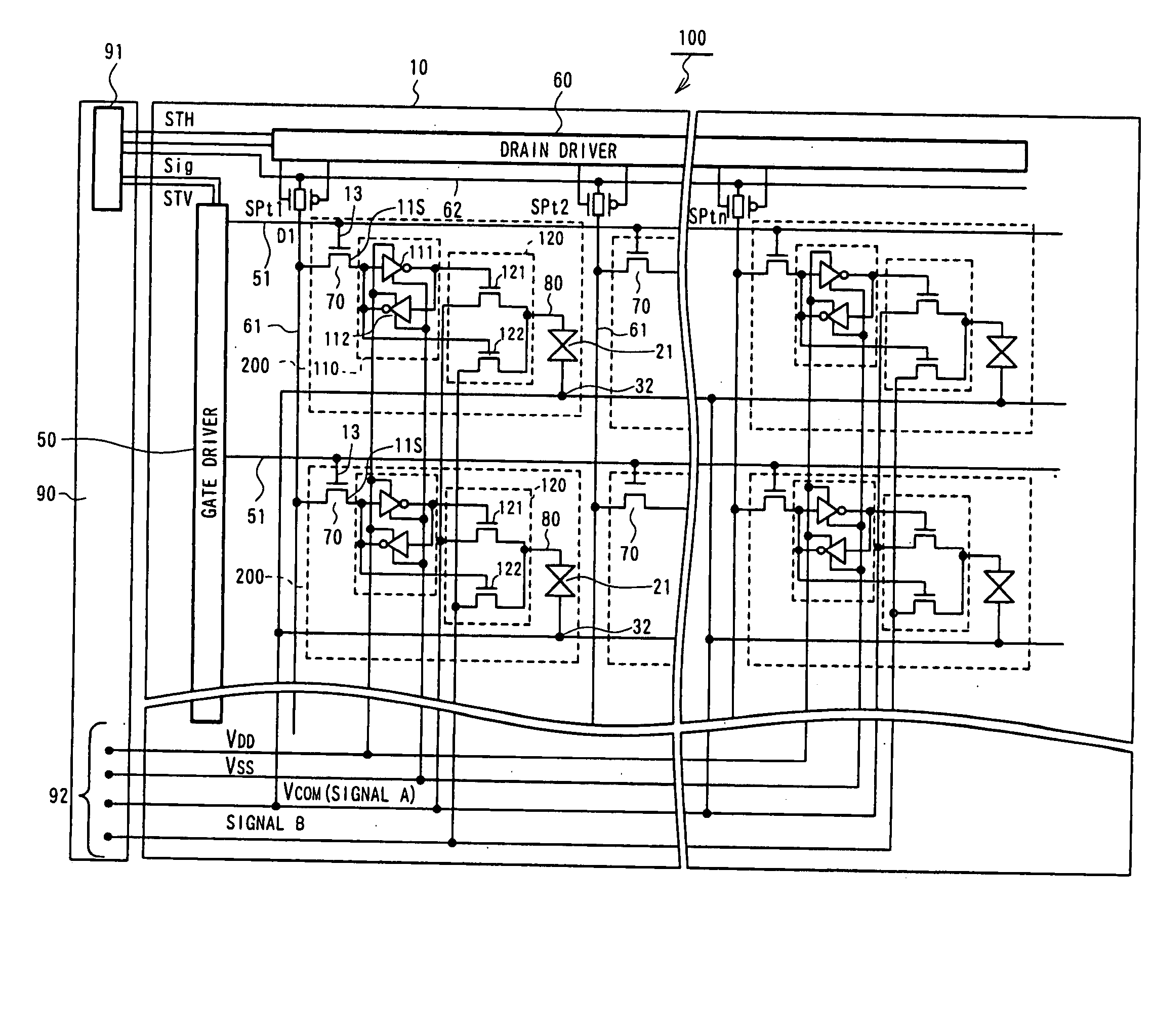
[0069] In the first embodiment, when data for one screen is written to all of the pixels as described above, that is, when a screen is displayed, voltage supplies to the gate driver 50, drain driver 60, and external LSI 91 for driving the panel are stopped to stop the operation of these components. The storing circuit 110 of each of the display pixels, on the other hand, is constantly supplied with voltages VDD and VSS to continue the data storage operation. VCOM is supplied to the facing electrode 32, as is normally done, and supply of each of the signals A and B to the selector 120 of each of the display pixels is also continued.

[0070] In other words, voltages VDD and VSS for driving the storing circuit 110 are supplied to the storing circuit 110 and the facing electrode voltage VCOM (signal A) which is a direct current voltage is applied to the facing electrode. When the liquid crystal display panel 100 is of the normally white (NW) type, the voltages supplied as the signal A and...

second embodiment

[0089] In this second embodiment, the drain signal supplied from the drain line 61 to the source 11s of the TFT 70 is accumulated in the capacitor 130. The drain signal is also input to the inverter 111, and the output signal from the inverter 111 is supplied to the other inverter 112 and to the gate of the first TFT 121 of the signal selector 120. The other inverter 112 inverts the output signal from the inverter 111 and outputs the inverted signal to the gate of the second TFT 122 in the signal selector 120.

[0090] The drain signal supplied via the TFT 70 is stored by the capacitor 130 and a selected signal is output from the inverters 111 and 112 based on the stored data. With a storing circuit 110 of such structure, the data signal can be stored similar to the storing circuit of FIG. 2A.

[0091] The operation of the selector 120 is identical to that for the first embodiment, and thus, the display apparatus of the second embodiment can display a still image even when the drivers 50...

fourth embodiment

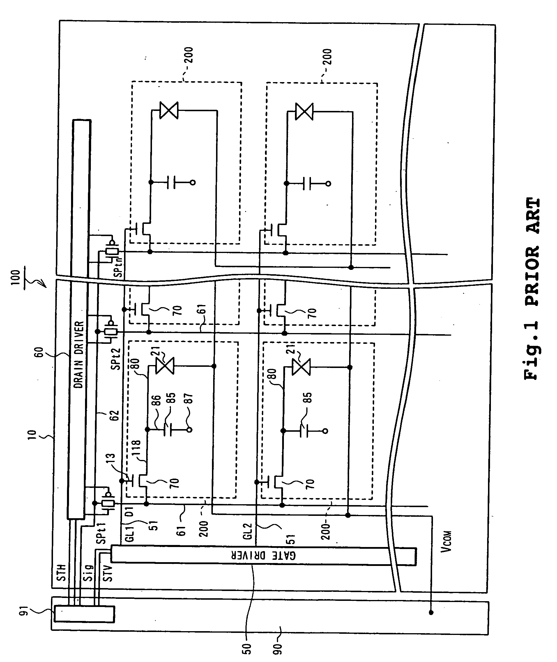
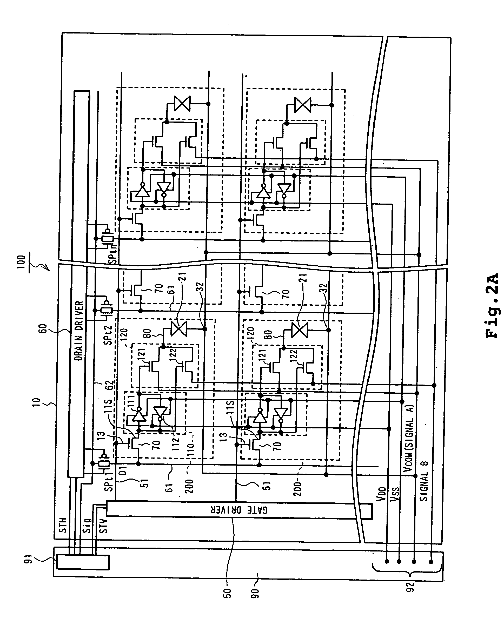
[0101]FIG. 6 shows a circuit configuration of a display apparatus according to the present invention, using an example applied to a liquid crystal display apparatus.

[0102] A plurality of gate lines 51 are provided in one direction of an insulating substrate 10. The gate lines 51 are connected to a gate driver 50 for supplying scan signals. A plurality of drain lines 61 are also provided on the substrate 10 in a direction intersecting with the gate lines 51.

[0103] A data signal from data line 62 (an analog image signal or a digital image signal) is supplied on the drain line 61 by turning sampling transistors SPt1 through SPtn on in response to sampling pulses which are output from a drain driver 60.

[0104] On a liquid crystal display panel 100, a plurality of display pixels 200 are provided in a matrix form, which is selected by a scan signal from the gate line 51 and which is supplied with data signals from the drain line 61.

[0105] An example configuration of the display pixel 20...


PUM

PropertyMeasurementUnit
voltageaaaaaaaaaa
sizeaaaaaaaaaa
weightaaaaaaaaaa

Abstract

A plurality of gate lines (51) connected to a gate driver (50) for supplying gate signals and a plurality of drain lines (61) connected to a drain driver (60) for supplying drain signals are provided on a substrate (10). Pixels (200) are formed in the regions surrounded by these lines. Each of the pixels (200) includes a TFT (70), a storing circuit (110) connected to the source (11s) of the TFT (70) for storing a digital signal, and a signal selector (120) for selecting a signal A or signal B in response to the signal stored in the storing circuit (110) and supplying the selected signal to a display electrode (80). Once a digital signal corresponding to a display image is written to the storing circuit (110) of each pixel (200), an image can be continuously displayed, even when operation of the drivers (50, 60) is stopped from the next frame, by continuing the operation of the storing circuit (110). Because the driver operation or the like can be suspended, overall power consumption can be reduced.

Description

BACKGROUND OF THE INVENTION [0001] 1. Field of the Invention [0002] The present invention relates to a display apparatus with a thin film transistor (abbreviated as “TFT” hereinafter). [0003] 2. Description of the Related Art [0004] Recently, there have been a great demand for a portable display apparatuses such as, for example, portable television sets and portable phones, and, consequently, there is great demand to reduce the size, weight, and power consumption in these portable display apparatuses. Considerable effort has been devoted to satisfying this demand. [0005]FIG. 1 is an equivalent circuit diagram of a conventional liquid crystal display apparatus. [0006] As shown in FIG. 1, a liquid crystal display panel 100 includes a plurality of gate lines 51 connected to a gate driver 50 for supplying gate signals, a plurality of drain lines 61 to which data signals on data lines 62 are supplied when sampling transistors SPt1, SPt2, . . . SPtn are switched on in response to respecti...

Claims


Application Information

Patent Timeline
Patent Type & Authority Applications(United States)
IPC IPC(8): G09G3/36G02F1/133G09G3/20
CPCG09G3/2011G09G3/3648G09G2300/0814G09G2300/0828G09G2300/0842G09G2300/0857G09G2310/04G09G2330/021G09G2330/022G09G2340/0428G02F1/133
Inventor YOKOYAMA, RYOICHI
Owner SANYO ELECTRIC CO LTD
Why Eureka
Try Eureka