Double-blade type decorative wheel for automobile wheel

A double-bladed, decorative wheel technology, applied to wheels, wheel cover plates, vehicle parts, etc., can solve the problems of general decorative effect and weak dynamics, and achieve the effect of clear dynamics, improved grades, and increased overall aesthetics

Inactive Publication Date: 2006-12-13
张援朝 +1
View PDF0 Cites 0 Cited by
  • Summary
  • Abstract
  • Description
  • Claims
  • Application Information

AI Technical Summary

Problems solved by technology

But the blades on the existing rotating parts installed on the wheels can only rotate in a single direction, the dynamic feeling is not strong, and the decorative effect is general

Method used


Image

  • Double-blade type decorative wheel for automobile wheel

Examples


Embodiment Construction

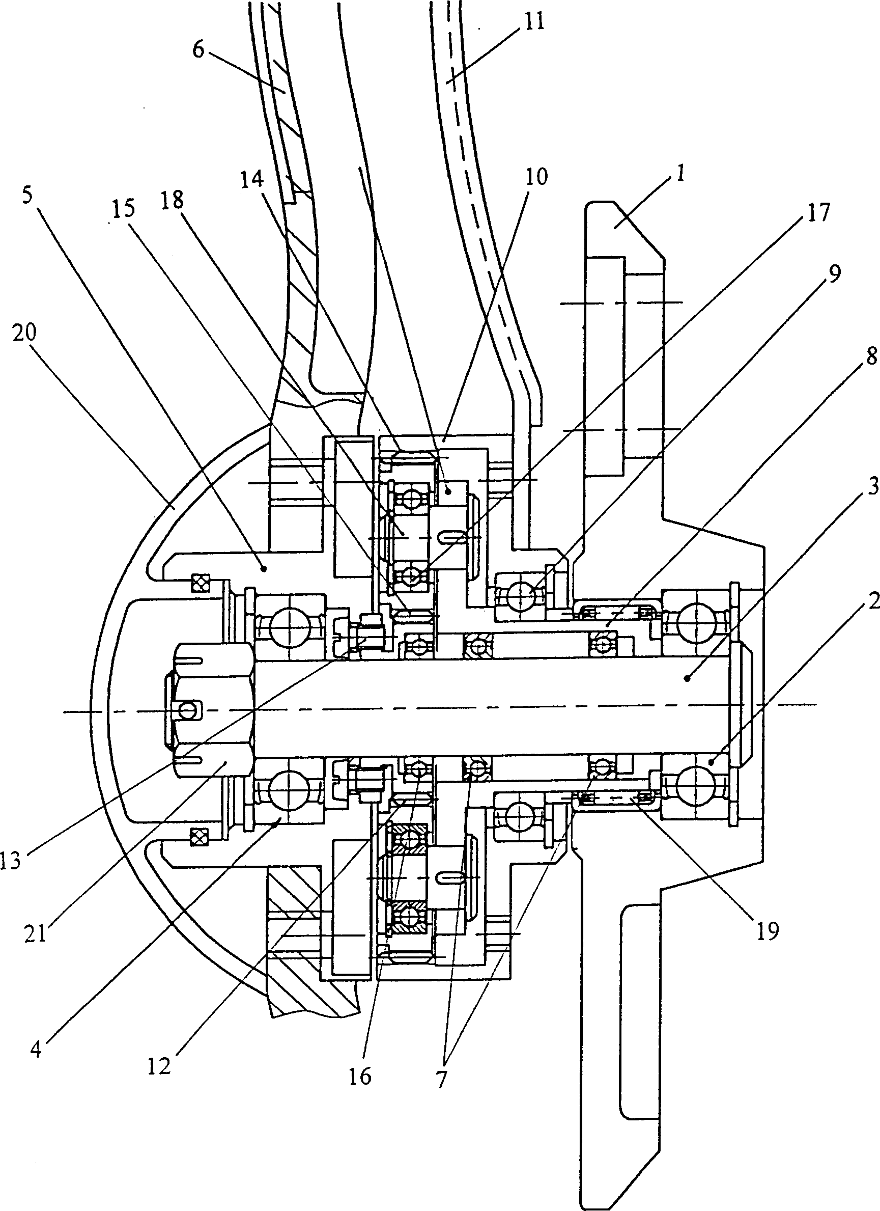
[0012] The present invention will be further described below in conjunction with the accompanying drawings and embodiments.

[0013] Such as figure 1 As shown, a double-bladed decorative wheel for automobile wheels includes a connecting disc 1, which is connected to the outer cover of the automobile wheel, and a main bearing 2 is installed at the center of the end of the connecting disc 1 near the wheel, and one end of the central shaft 3 Supported in the main bearing 2, the other end is equipped with an outer impeller bearing 4, and the outer impeller frame 5 is set on the outer impeller bearing 4, and the number is five. It is an integral structure, and it can also be a split structure, and decorative nails can also be installed on the outer blade 6 to increase its decorative effect. Two inner impeller bearings 7 are installed on the central shaft 3 near one end of the main bearing 2, and the inner frame 8 of the inner impeller is sleeved on the two inner impeller bearings ...


PUM


Abstract

A decorative wheel with double impellers is used in used on vehicle wheels. The double impellers rotate in a same direction when a vehicle runs, and rotate ni opposite directions when a vehicle stops. It consists of a connecting disc equipped with a primary bearing centrally at the size of the wheel, a spindle installed in the bearing, the inner and outer impellers installed on the spindle. A gear transmission is used to drive the impellers.

Description

technical field [0001] The invention relates to an automobile accessory, in particular to a decorative article mounted on an automobile wheel, specifically a kind with two sets of decorative blades, and when parking, the two sets of decorative blades can rotate in opposite directions. Decorative wheels for rotating two-bladed car wheels. Background technique [0002] At present, the decoration of automobile wheels, as an important part of automobile decoration, has been paid more and more attention by people. The aesthetics of the wheels is conducive to improving the grade of the vehicle. However, the existing blades installed on the rotating parts on the wheels can only rotate in a single direction, and the dynamic feeling is not strong, and the decorative effect is general. Contents of the invention [0003] The purpose of the present invention is to provide a better decorative effect and a stronger dynamic feeling with inner and outer blades. When the wheel rotates, t...

Claims


Application Information

Patent Timeline
Patent Type & Authority Patents(China)
IPC IPC(8): B60B7/20
Inventor 朱广圣
Owner 张援朝
Why Eureka
Try Eureka