
Rubber crawler belt

A rubber crawler and crawler technology, applied to tracked vehicles, power steering mechanisms, steering mechanisms, etc., can solve problems such as foreign matter intrusion, rubber membrane damage, and slit damage

Inactive Publication Date: 2006-12-20
SUMITOMO RUBBER IND LTD +1
View PDF4 Cites 0 Cited by
  • Summary
  • Abstract
  • Description
  • Claims
  • Application Information

AI Technical Summary

Problems solved by technology

[0010] Furthermore, if the rubber film forms a slit, foreign matter will enter through the slit, and these intrusions will damage the rubber film, especially the slit will accelerate the breakage

Method used


Image

  • Rubber crawler belt
  • Rubber crawler belt
  • Rubber crawler belt

Examples


Embodiment Construction

[0038] Hereinafter, embodiments of the rubber crawler of the present invention will be described with reference to the drawings.

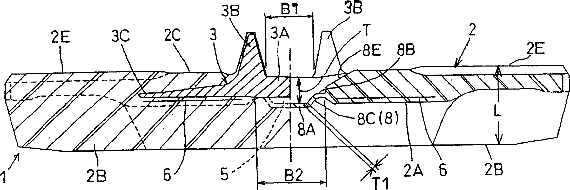
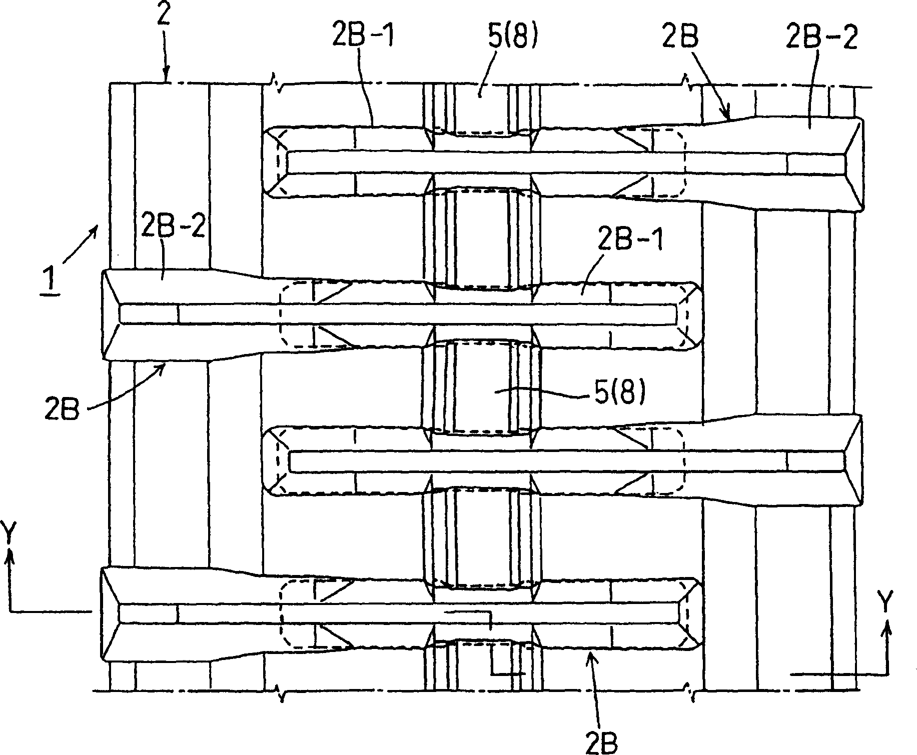
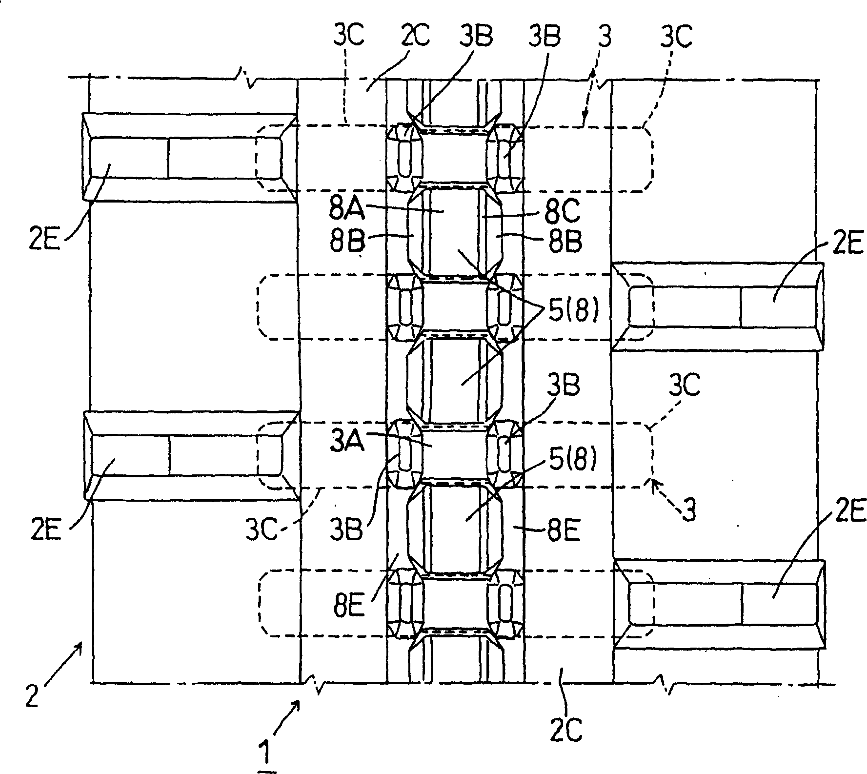
[0039] figure 1 It is a cross-sectional view of the main parts of the rubber track 1 ( figure 2 Y-Y cross-sectional view), figure 2 It is a plan view of the main part viewed from the ground plane (outer peripheral surface), image 3 It is a plan view of the main part viewed from the inner peripheral surface, and Fig. 4 is a side view of the wrapping part, as the first embodiment figure 1 - In FIG. 4 , the rubber crawler 1 is mainly composed of a jointless crawler body 2 substantially made of rubber, and horizontally placed cores (mandrels) 3 embedded in the crawler body 2 at intervals. The joint-shaped crawler body 2 is wound and driven by a driving sprocket (see FIG. 4 ) 4 and a driven pulley (idling pulley) not shown in the figure.

[0040]In the horizontal core body 3, there is a mated portion 3A that engages and disengages with the teet...


PUM


Abstract

The invention provides a rubber crawler belt, driving holes (5) matching to the driving sprocket (4) of an endless crawler belt (2) substantially formed of rubber material are provided with films (8) for closing the driving holes (5), the films (8) are composed of a film face portion (8A) substantially closing the driving holes (5), a rising film portion (8C) and a connecting portion (8B) to become tube shape, which can prevent the foreign body from invading into the inner circumference face of the endless crawler belt (2) from the driving holes (5), thereby preventing the generating of the mud block.

Description

technical field [0001] The invention relates to a rubber crawler (also called an elastic crawler), which is used in crawler-driven traveling devices of agricultural machinery such as combine harvesters and construction machinery such as excavators. Background technique [0002] The track-driven drive units of agricultural and construction machines consist of, for example Figure 11 As shown in (1) and (2), the jointless crawler body A, which is all substantially rubber, is wound on the drive sprocket (drive sprocket) J and the driven wheel K, and the teeth of the drive sprocket J are consistent with the The drive holes arranged at intervals in the belt length direction of the belt body cooperate with each other and disengage for circular transmission. [0003] Figure 10 shows the main parts of the traveling device. A is a jointless crawler body, and horizontal cores B are embedded at intervals in the belt length direction, and the teeth of the driving sprocket are matched wi...

Claims


Application Information

Patent Timeline
Patent Type & Authority Patents(China)
IPC IPC(8): B62D55/24B62D55/253B62D5/00B62D6/02
CPCB62D5/008B62D6/02B62D55/24
Inventor 吉田知久平田和嘉
Owner SUMITOMO RUBBER IND LTD
Learn More