Supercharge Your Innovation With Domain-Expert AI Agents!

Driving apparatus for insertion type circuit breaker

A transmission device and circuit breaker technology, which is applied to high-voltage air circuit breakers, switchgear, switchgear components, etc., can solve the problems of not being able to find the hand crank, and the hand crank cannot be used, and achieve the effect of avoiding improper use.

Inactive Publication Date: 2007-01-17
SIEMENS AG
View PDF5 Cites 0 Cited by
  • Summary
  • Abstract
  • Description
  • Claims
  • Application Information

AI Technical Summary

Problems solved by technology

However, the experience in the operation of electrical equipment has proved that sometimes there is still a situation where the required hand crank cannot be found or the found hand crank cannot be used.

Method used


Image

  • Driving apparatus for insertion type circuit breaker
  • Driving apparatus for insertion type circuit breaker
  • Driving apparatus for insertion type circuit breaker

Examples


Embodiment Construction

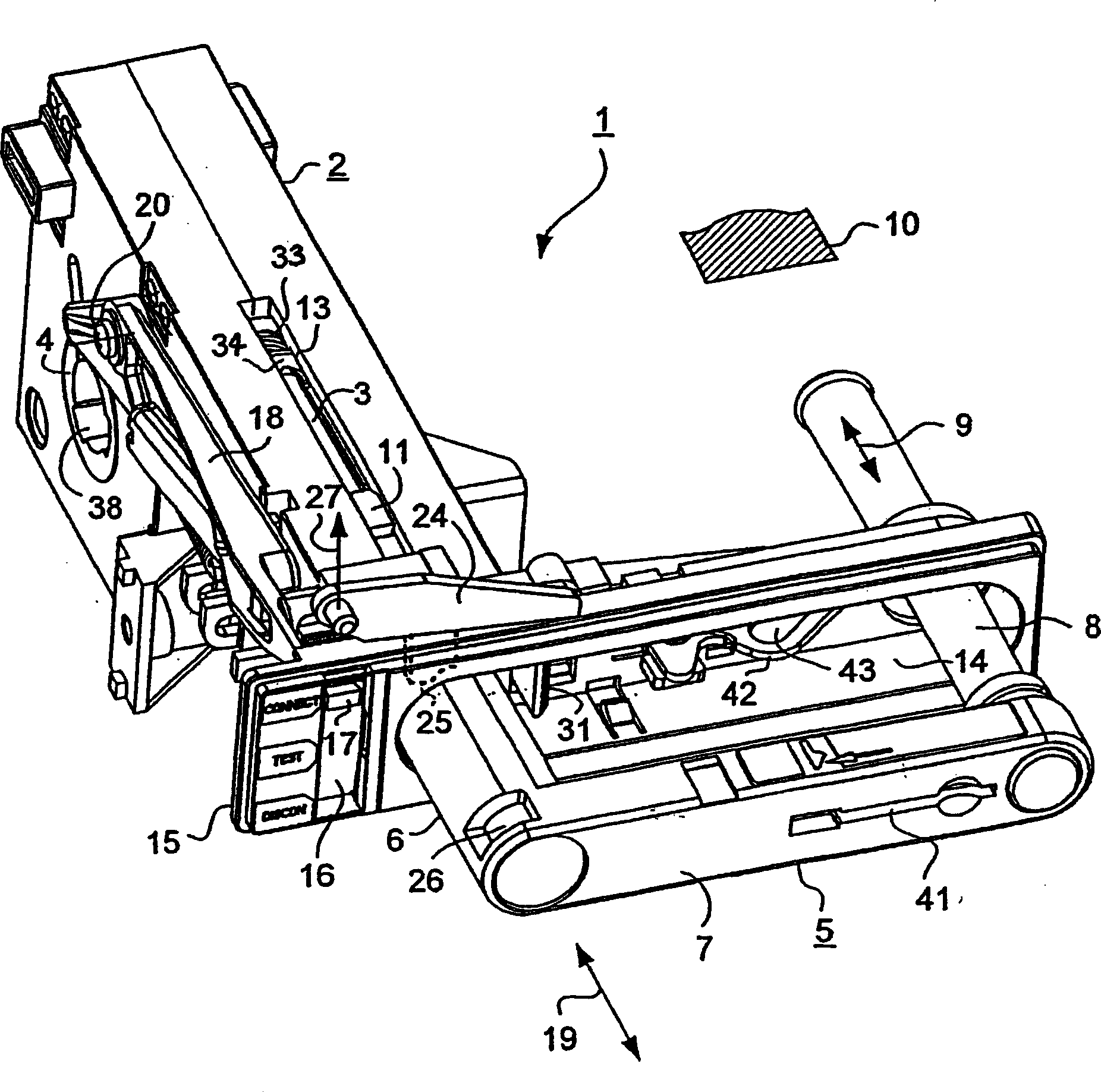
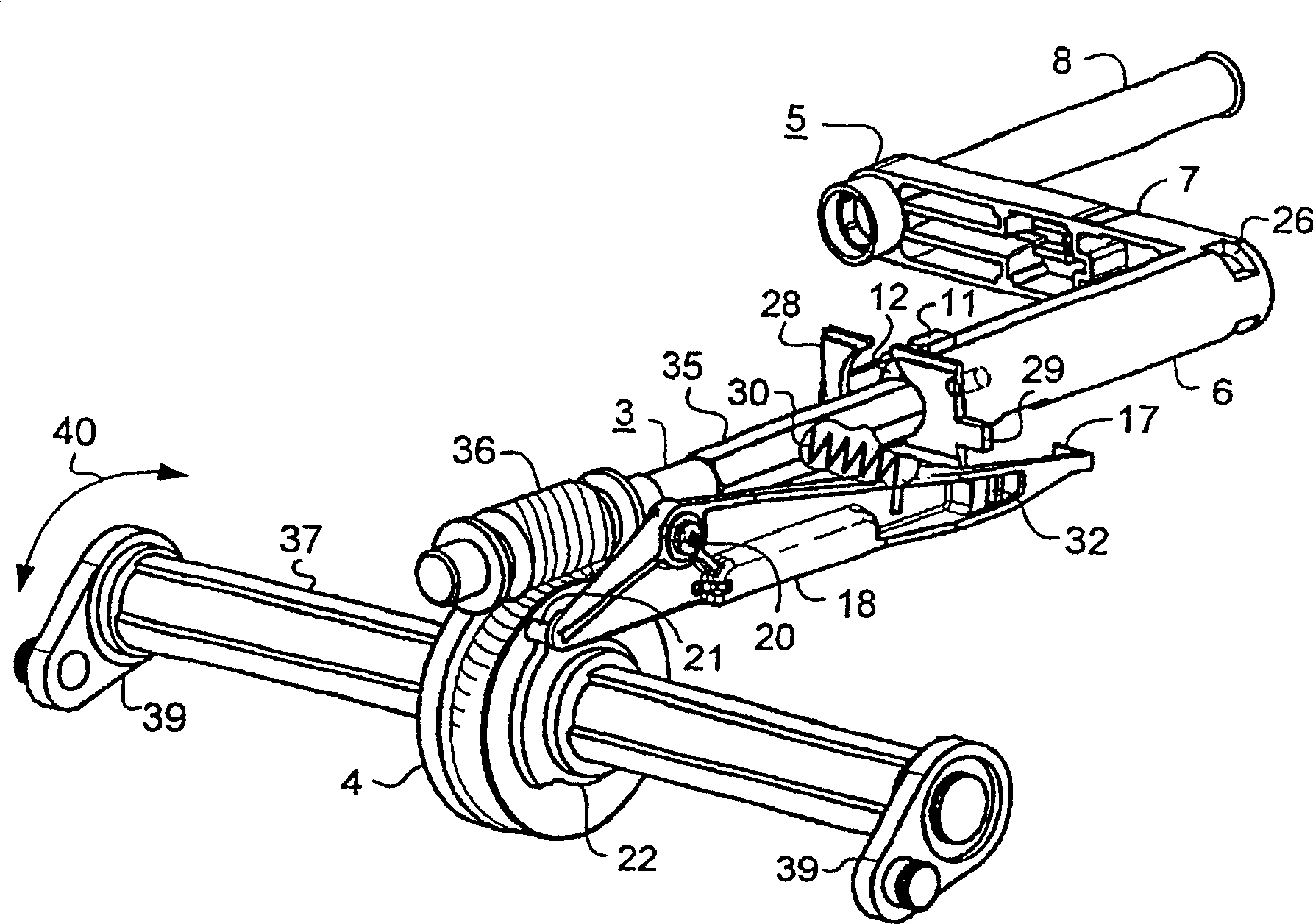
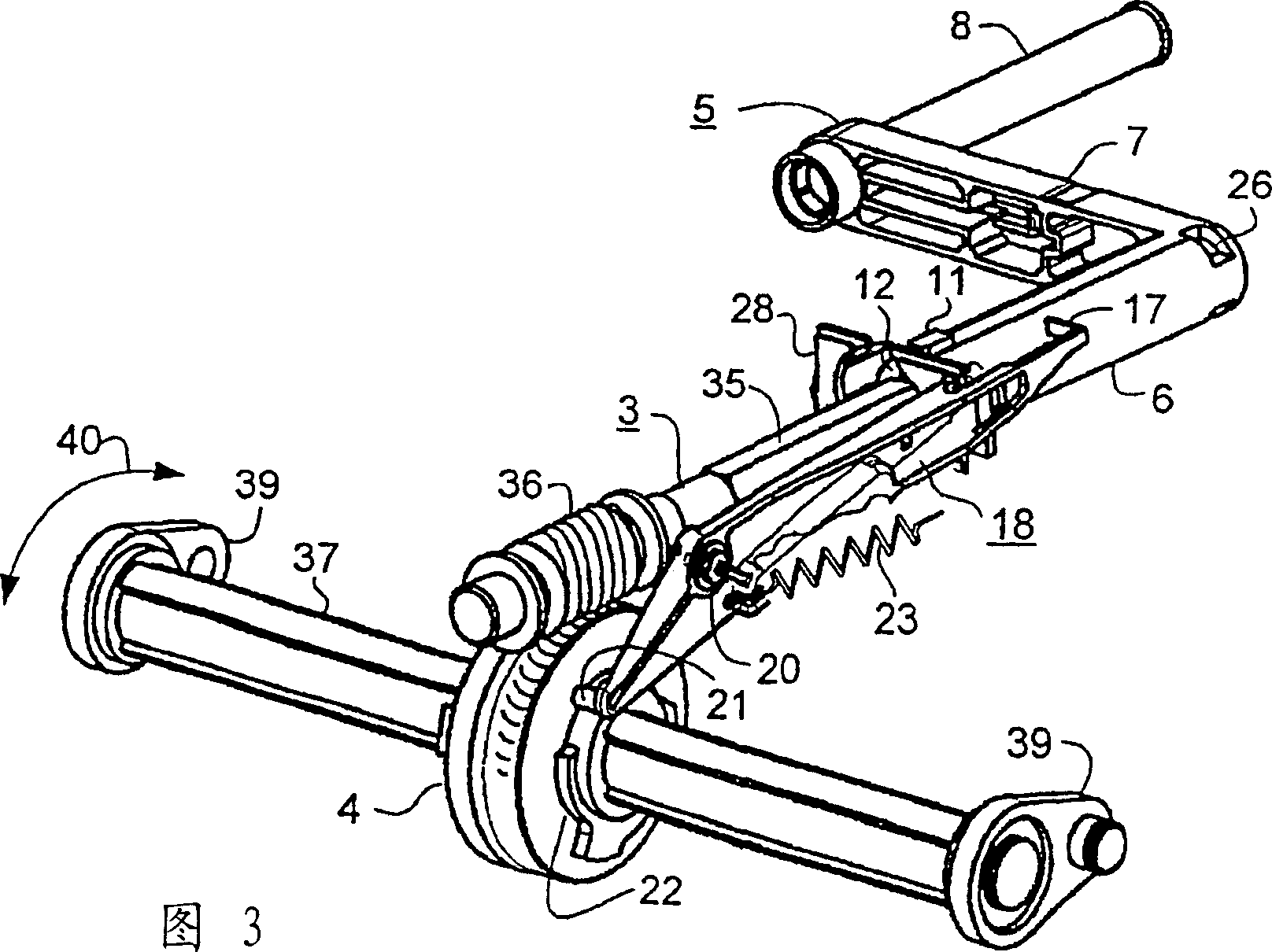
[0022] figure 1 The transmission 1 shown has a housing 2 which may consist of two suitable half-shell parts, between which transmission components and other components are mounted. The rotation achieved by means of the hand crank 5 is via the drive shaft 3 (see also figure 2 and Fig. 3) into the rotation of transmission shaft 37 (see figure 2 and Figure 3). For this purpose, a worm 36 which meshes with the drive worm gear 4 is arranged on the drive shaft 3 . The longitudinal axis of the drive shaft 3 is perpendicular to the transmission shaft 37 . The transmission shaft 37 is not fixedly connected with the transmission device 1 , but can move in the forming hole 38 of the transmission worm wheel 4 , and the forming hole 38 is adapted to the shape of the transmission shaft 37 . In this way the transmission 1 can be used for circuit breakers of different sizes and not necessarily connected at a given position along the transmission shaft 37 . On both ends of the drive sha...


PUM


Abstract

A travelling mechanism (1) for a withdrawable circuit-breaker comprises a crank handle (5) that is secured in a manner that prevents it from being removed. A shaft (6) of the crank handle (5) revolves around an input shaft (3) and is guided in a manner that permits it to be displaced in relation thereto. An accommodating recess (14) holds the crank handle (5) in its inoperative position. In its working position, the crank handle (5) can only be pulled out when a locking lever (24) that is dependent on the switching position of the circuit-breaker releases a locking slot (26) on the shaft (6) of the crank handle (5). In the working position, the crank handle (5) is secured by a locking slide. An indicating device for indicating the position of the circuit-breaker comprises a two-armed indicating lever (18), which is provided with a window opening (32) that permits the entry of a tongue (29) of the locking slide (28) in the test position.

Description

technical field [0001] The invention relates to a transmission for use in plug-in circuit breakers, which has a drive shaft operated by a hand crank, and a drive shaft that converts the rotational movement of the drive shaft into rotation of a drive shaft arranged perpendicular to the drive shaft The transmission mechanism, and a display member for displaying the state of the circuit breaker related to the main and auxiliary separation contacts. Background technique [0002] A transmission of this type is known from DE 44 20 584 C1. In order to insert or pull the circuit breaker into or out of the associated insertion chamber, the drive shaft is provided with a shaped end piece on which the hand crank can be attached. Occasionally there may be a sudden need to operate the hand crank, so it must be readily available so that it can be used when needed. However, the experience of electrical equipment operation proves that sometimes there is still a situation where the require...

Claims


Application Information

Patent Timeline
Patent Type & Authority Patents(China)
IPC IPC(8): H02B11/127H02B11/10H01H33/46H02B11/133H02B11/167
CPCH02B11/127
Inventor 埃哈德·戴伊利兹
Owner SIEMENS AG
Features
  • R&D
  • Intellectual Property
  • Life Sciences
  • Materials
  • Tech Scout
  • Unparalleled Data Quality
  • Higher Quality Content
  • 60% Fewer Hallucinations
Learn More