
Drive unit and method for single-phase switch type magnetic resistance motor

A technology of reluctance motor and driving method, which is applied in the field of motors, and can solve the problems of not being able to stop, not being able to use the stop magnet, and failure to start next time

Inactive Publication Date: 2007-02-14
LG ELECTRONICS (TIANJIN) APPLIANCES CO LTD
View PDF2 Cites 0 Cited by
  • Summary
  • Abstract
  • Description
  • Claims
  • Application Information

AI Technical Summary

Problems solved by technology

[0017] The single-phase SRM provided by the prior art cannot stop at the correct position when stopped after being driven in the state connected to the load, that is, it cannot be located at the stop position by the magnetic force generated by the stop magnet, thus, it will give the next The hidden danger of failure caused by the first start

Method used


Image

  • Drive unit and method for single-phase switch type magnetic resistance motor
  • Drive unit and method for single-phase switch type magnetic resistance motor
  • Drive unit and method for single-phase switch type magnetic resistance motor

Examples


Embodiment Construction

[0029] Hereinafter, the present invention will be described in more detail with reference to the drawings.

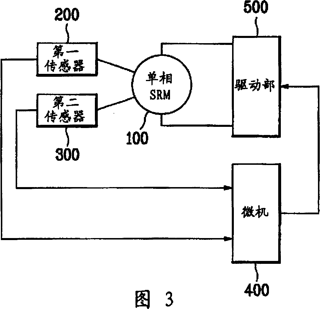
[0030] Fig. 3 is a block diagram showing the structure of a single-phase SRM drive device according to the present invention, Figure 4 It is a flowchart showing the single-phase SRM driving method related to the present invention, Figure 5 It is a waveform diagram explaining the single-phase SRM driving method according to the present invention.

[0031] As shown in FIG. 3, the structure of the single-phase SRM drive device according to the present invention includes: a single-phase SRM 100; a first sensor 200 for detecting the rotation speed of the single-phase SRM 100 and the rotor position for low-speed driving; The second sensor 300 for the position of the rotor for driving; judges whether the rotor is in the correct position based on the output of the first sensor 200 and the second sensor 300 and the rotation speed of the single-phase SRM, and if it is judged to be n...


PUM


Abstract

A single phase SRM drive and its method contains a single phase SRM used in testing the said single phase SRM motor rotating speed and a first transducer of the position of rotor in low speed drive and testing a second transducer of the rotor position in high speed driving. It also contains to judge if the rotor is at the correct position according to the output of the said first and second transducers and the said motor rotating speed then to output correcting signals enabling the rotor at the right position when judging the rotor is not at the right position or to output driving signal to the microcomputer, provide the correcting signal related to the said microcomputer outupt and power of driving signal then to drive driving part of the said single phase SRM motor.

Description

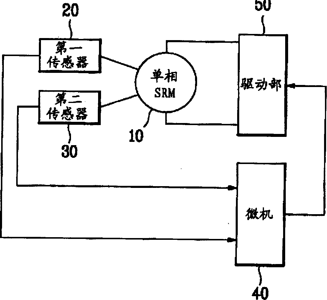
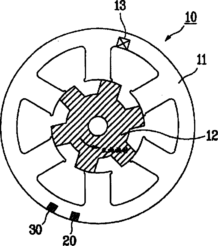
Technical field [0001] The present invention relates to a motor, in particular to a driving device and method for a single-phase switched reluctance motor (Switched Reluctance Motor: SRM for short). Background technique [0002] Generally speaking, SRM can be divided into single-phase, two-phase, and three-phase. Although two-phase or three-phase has no problems in driving, it is difficult to apply in reverse phase due to the high cost of driving components such as IGBT. On the device, although the structure and drive circuit of the single-phase SRM are simple, low-cost and easy to implement, there is also a problem that it cannot be started due to the difference in the position of the rotor. [0003] In summary, the structure of the single-phase SRM drive device using the prior art is as follows figure 1 As shown, it is composed of the following parts: a single-phase SRM; a first sensor for detecting the rotation speed of the single-phase SRM and a rotor p...

Claims


Application Information

Patent Timeline
Patent Type & Authority Patents(China)
IPC IPC(8): H02P6/00H02P6/24H02P6/16H02P6/26
Inventor 郑泰旭文昶琇金相斗
Owner LG ELECTRONICS (TIANJIN) APPLIANCES CO LTD
Learn More