Eureka AIR delivers breakthrough ideas for toughest innovation challenges, trusted by R&D personnel around the world.

Pressure rising type fuel expulsion system

A fuel injection system, pressure technology, applied in the direction of fuel injection control, fuel injection device, charging system, etc., can solve problems such as damage to the engine or vehicle, trouble, failure of fuel pressure control parts, control units or other parts, etc. Achieve the effect of protecting vibration and preventing insufficient purification

Inactive Publication Date: 2007-03-07
MITSUBISHI FUSO TRUCK AND BUS CORPORATION
View PDF5 Cites 0 Cited by
  • Summary
  • Abstract
  • Description
  • Claims
  • Application Information

AI Technical Summary

Problems solved by technology

However, the troubleshooting device can only detect abnormal cylinders, but cannot determine whether the fuel pressure control, control unit or other parts are faulty
This means that it is somewhat troublesome to take proper action in an emergency, which could damage the engine or the vehicle

Method used


Image

  • Pressure rising type fuel expulsion system
  • Pressure rising type fuel expulsion system
  • Pressure rising type fuel expulsion system

Examples


Embodiment Construction

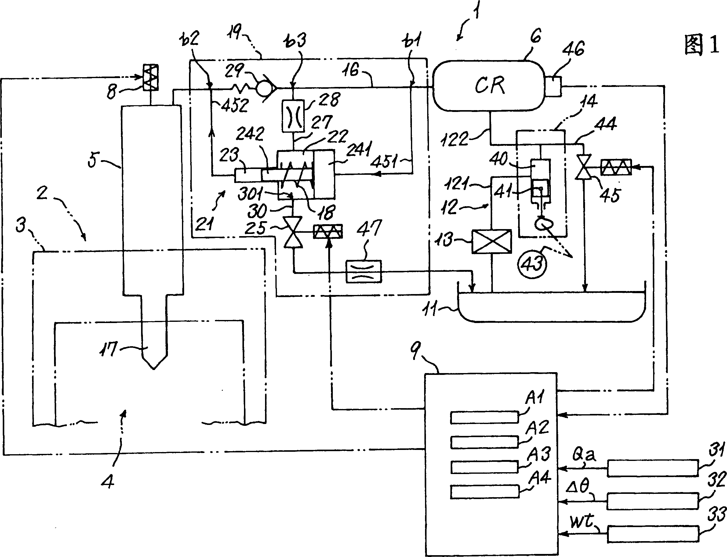
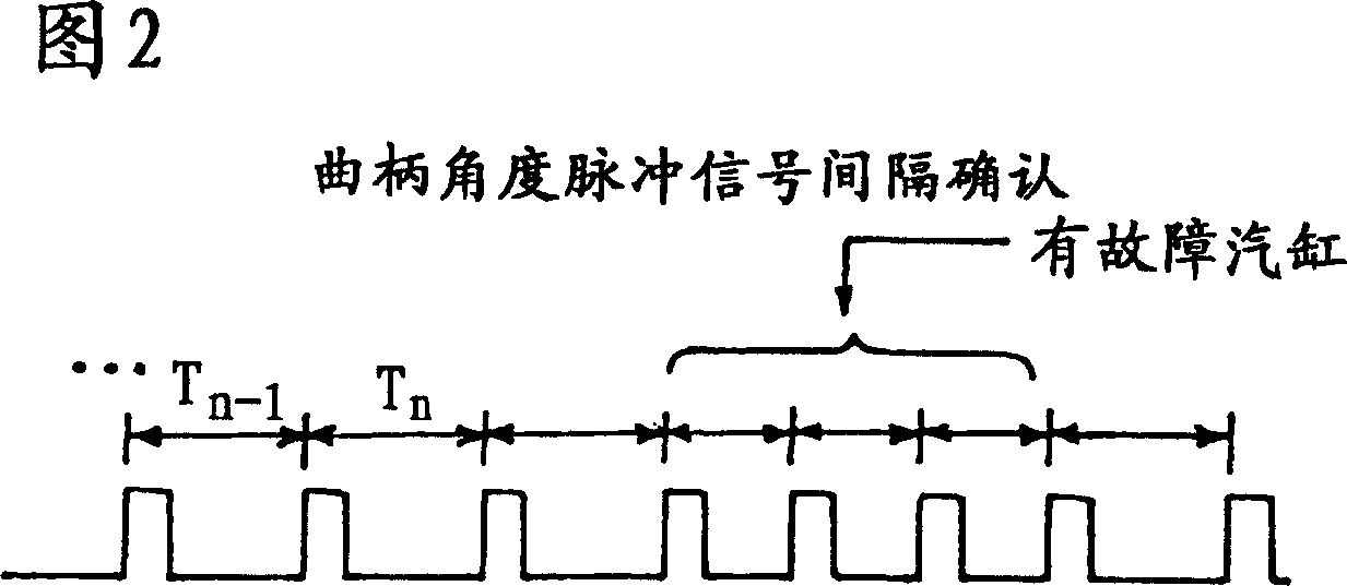
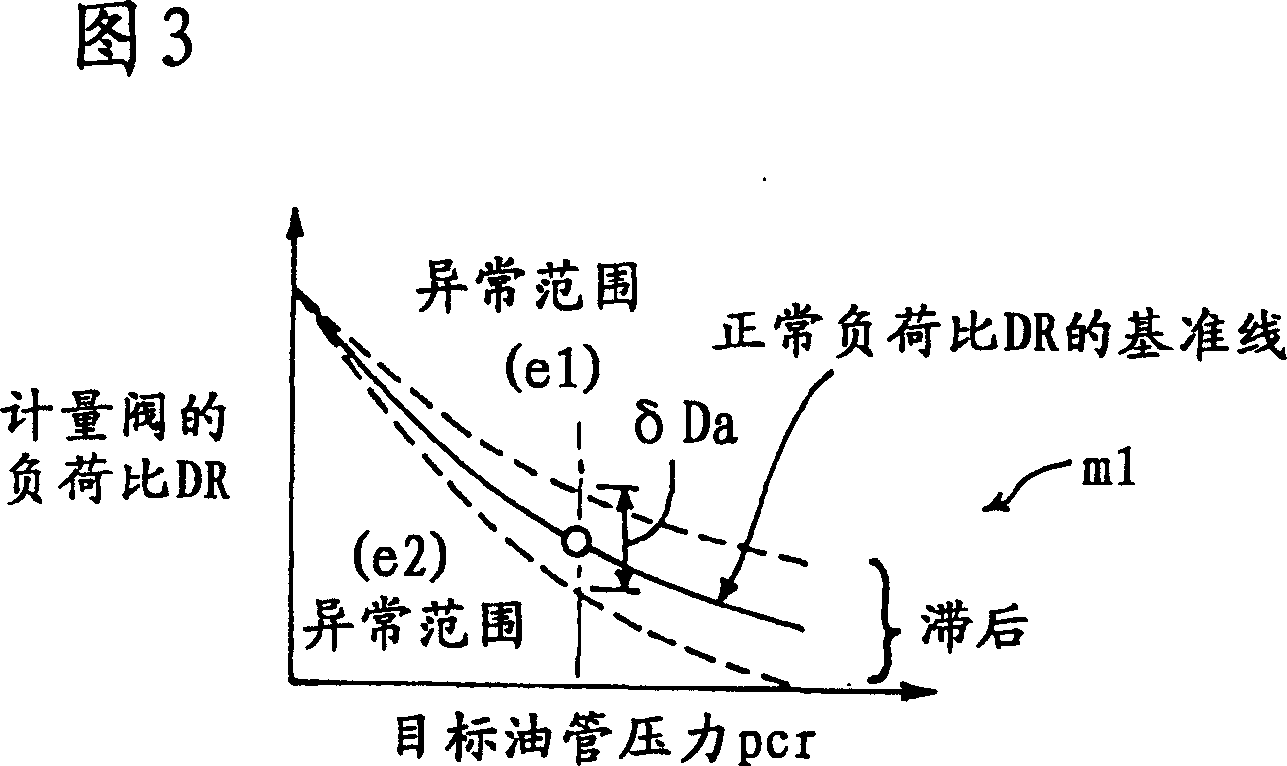
[0024] The present invention will be described with reference to an embodiment shown in FIGS. 1 to 3.

[0025] A pressure-increasing fuel injection system 1 is installed in an unshown multi-cylinder diesel engine 2 (called "engine 2"). Specifically, the pressure-increasing fuel injection system 1 (called "fuel injection system 1") is installed on the engine block 3 of the engine 2 and pressurized in the two-step injection mode M1 or the single-step injection mode M2 ​​described later Fuel is injected into the combustion chamber 4 in the engine block 3.

[0026] The fuel injection system 1 includes: an injector 5 to inject fuel into each combustion chamber 4 in the engine body 3; a common fuel pipe 6 to supply high-pressure fuel to the injector 5; a high-pressure fuel source 7 to High-pressure fuel is supplied to the common supply pipe 6; and an engine controller 9 that controls the operation of the injector solenoid valve 8 of the injector 5.

[0027] The high-pressure fuel source...


PUM


Abstract

Provides is a boosting fuel injection device. In this fuel injection device, fuel is injected into a combustion chamber 4 by an injector 5 by selectively switching between fuel stored in a common rail 6 and boosted fuel boosted by the boosting mechanism 21 receiving the fuel. The device comprises a crank angle sensor 32 outputting crank pulse signals according to the operating state of an engine 2, a pulse calculation means A3 calculating a pulse width Tn between the crank pulse signals, and a determination means A4 determining that the boosting mechanism 21 is defective when the variation amount [delta]t of the pulse width Tn exceeds a determination threshold [delta]ta.

Description

Technical field [0001] The present invention relates to a pressure-increasing fuel injection system in which high-pressure fuel from a pressure accumulating chamber is further pressurized by a pressure-increasing mechanism and injected into a combustion chamber through an injector, and more specifically, to an even A pressure-increasing fuel injection system that can accurately inject fuel even when the pressure-increasing mechanism fails. Background technique [0002] A pressure-increasing fuel injection system is one of fuel injection systems that inject fuel into the combustion chamber of an internal combustion engine through an injector. In such a pressure-increasing fuel injection system, high-pressure fuel from a fuel source is stored in a common fuel supply pipe that functions as a constituted accumulator, and is connected to the injector nozzle and the combustion chamber on the common fuel supply pipe Facing. Furthermore, a pressure raising mechanism is arranged in a bran...

Claims


Application Information

Patent Timeline
Patent Type & Authority Patents(China)
IPC IPC(8): F02M47/00F02M63/00F02D45/00F02D41/22F02D41/38
CPCF02D41/3809F02D41/22F02D2041/223F02D2041/224
Inventor 田边圭树纐纈晋中山真治
Owner MITSUBISHI FUSO TRUCK AND BUS CORPORATION
Why Eureka
Eureka Blog
Learn More