
Guiding device for a flotation machine

A guiding device and flotation machine technology, applied in the field of flotation machines, can solve the problems of reducing the total efficiency and output of gas dispersion devices

Inactive Publication Date: 2007-05-02
OUTOTEC OYJ
View PDF4 Cites 0 Cited by
  • Summary
  • Abstract
  • Description
  • Claims
  • Application Information

AI Technical Summary

Problems solved by technology

This unnecessary circulation of dispersed gas in the gas dispersion unit reduces the overall efficiency and throughput of the gas dispersion unit

Method used


Image

  • Guiding device for a flotation machine
  • Guiding device for a flotation machine

Examples


Embodiment Construction

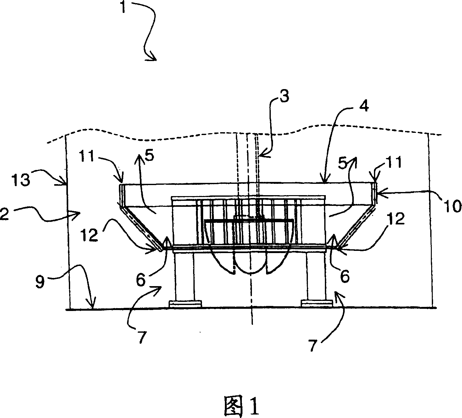
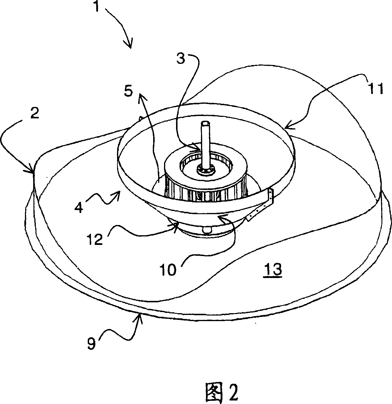
[0013] As shown in Figure 1, a flotation machine 1 includes at least one flotation cell 2, a gas dispersion device 3, a device for removing foam from the flotation cell and a device for removing tailings from the flotation cell, flotation The tank has a device for feeding the slurry into the tank; the gas dispersion device 3 is used to feed gas 5 into the slurry and generate foam. According to the invention, at least one guiding device 4 is installed close to the gas dispersing device 3 in order to lead the dispersed gas away from the gas dispersing device, preventing recirculation of the flotation gas into the suction zone 7 of the gas dispersing device 3 . The guiding device 4 is installed close to the gas dispersing device so that it guides the gas 5 away from the gas dispersing device. According to this example, the guiding means are conical and comprise a wall element 10 extending substantially symmetrically around the entire gas dispersing means 3 in the direction upward...


PUM


Abstract

A flotation machine (1) comprising at least one flotation cell (2), a gas dispersion device (3), a device for removing foam from the flotation cell and a device for removing tailings from the flotation cell , the flotation cell (2) has a device that feeds slurry into the flotation cell, and the gas dispersion device (3) is used to send gas into the slurry and generate foam, which is characterized in that it is located near the gas dispersion device (3) At least one guiding device (4) is installed in the position to guide the dispersed gas (5) from the gas dispersing device (3).

Description

technical field [0001] The present invention relates to a flotation machine comprising a flotation cell, a gas dispersing device, a device for removing tailings from the flotation cell, and a device for removing froth from the flotation cell. The flotation cell includes a set of devices that feed the slurry into the flotation cell, and the gas dispersion device is used to send gas into the slurry and generate foam. According to the invention, at least one guide device is arranged close to the gas dispersing device in order to guide the dispersed gas away from the gas dispersing device. Background technique [0002] The froth flotation machine is used to recover useful minerals, which usually have some kind of hydrophobic surface, and generally include a box-type flotation cell with an inlet on the wall of the cell for feeding the flotation slurry. There is also an outlet in the lower part of the tank for discharging tailings. Flotation cells can be multiple independent mix...

Claims


Application Information

Patent Timeline
Patent Type & Authority Patents(China)
IPC IPC(8): B03D1/16B03DC02F1/24
CPCB03D1/1412C02F1/24B03D1/16
Inventor C·库加瓦
Owner OUTOTEC OYJ
Learn More