
Nozzle of a turbomachine provided with chevrons with a non-axisymmetric inner face

a turbomachine and inner face technology, applied in the direction of machines/engines, mechanical equipment, transportation and packaging, etc., can solve the problems of inconvenient incorporation of anti-noise chevrons in the trailing edge region of the nozzle, noise, and generally designated as “jet noise” and other problems, to avoid disruption of internal flow, avoid recirculation, and improve the re-entrant nature of the chevrons

Active Publication Date: 2019-05-28
SN DETUDE & DE CONSTR DE MOTEURS DAVIATION S N E C M A
View PDF13 Cites 0 Cited by
  • Summary
  • Abstract
  • Description
  • Claims
  • Application Information

AI Technical Summary

Benefits of technology

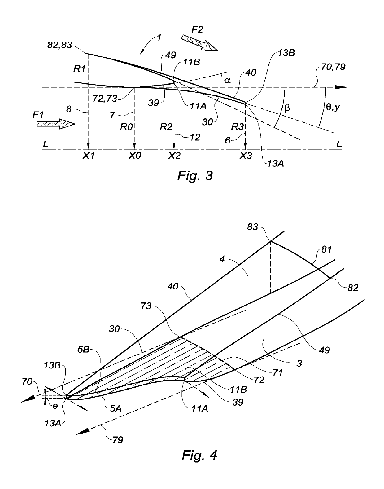
[0023]On the one hand, the convergent design of the chevrons makes it possible to optimise them for reduction of the noise. On the other hand, the tops of the indentations can diverge from the axis regardless of the shape of the cross-section in the region of the chevrons, without taking account for example of the structural stresses of thickness of the cowl in the region of the chevrons. This makes it possible to obtain a larger equivalent discharge cross-section than in the previous solutions. This discharge cross-section is an important parameter in order to ensure the performance levels of the nozzle in various operating conditions, for example in order not to restrict the flow rate coefficient. In a way, the invention makes it possible to separate the geometric design parameters of the nozzle between those governing the acoustic performance levels and those governing the operational performance levels. The fact that the divergence of the external wall decreases constantly towards the top of the indentations makes it possible to decrease the separation of the external flow in this zone and thus contributes to the operational effectiveness of the nozzle. Another advantage of the invention is that it makes it possible to eliminate the part of maximum internal cross-section of the nozzle in the chevrons, corresponding to a possible separation zone.
[0024]The lines defining the internal wall of the cowl upstream and downstream of the neck line in any axial half-plane preferably have the same tangent on this neck line. This avoids disruptions in the internal flow.
[0025]The line defining the internal wall of the cowl downstream of said determined abscissa X0 in an axial half-plane passing through the tip of a chevron is preferably concave when viewed from the axis L-L, with a view to improving the re-entrant nature of the chevron and avoiding recirculation zones in the internal flow.
[0026]The line defining the internal wall of the cowl downstream of said determined abscissa X0 in an axial half-plane passing through the top of an indentation is preferably convex when viewed from the axis L-L. This accords with the fact that the internal shape of the cowl forces the internal flow to diverge in this zone and to meet the external flow opposite a confluence where the two flows would be substantially parallel.
[0027]The line defining the external wall of the cowl downstream of said determined abscissa X0 in an axial half-plane passing through the top of an indentation is also preferably concave when viewed from the axis L-L. This condition reinforces the condition on the overall convergence of the external wall in an indentation in order to indicate that the direction imposed by the external wall at the top of the indentation on the external flow is re-entrant with respect to the mean direction of the internal flow.
[0028]Advantageously, the lines defining the external wall of the cowl in any axial half-plane do not have a turning point downstream of said determined abscissa X0 of the neck line, in order to limit the risks of separation in the external flow.

Problems solved by technology

The speed difference between the jet at the nozzle outlet and the other gaseous flow or flows which it encounters creates fluid shears penetrating between these gaseous flows, which causes noise, commonly designated as “jet noise”.
This “jet noise” is a broadband noise which is particularly inconvenient during the aeroplane take-off phase.
However, the incorporation of anti-noise chevrons in the region of the trailing edge of the nozzle is not entirely satisfactory.
In fact, a pronounced inclination of the chevrons towards the outlet jet is generally necessary in order to obtain an acceptable reduction of the jet noise, which leads to a deterioration of performance levels, in particular the thrust, of the turbine engine at its different operating speeds.
In addition, by decreasing the effective discharge cross-section of the internal gaseous flow of the nozzle, the inclination of the chevrons reduces the thrust ratio of the turbine engine between the take-off speed and the cruising speed.
This results in a loss of operability of the turbine engine.
This problem is particularly significant in the case of a convergent-divergent nozzle designed to optimise this operability.
However, this design does not allow sufficient degrees of freedom in order to treat all cases and has drawbacks for the internal flow, creating a possible recirculation zone in the zone where the chevrons curve in order to become convergent again.

Method used


Image

  • Nozzle of a turbomachine provided with chevrons with a non-axisymmetric inner face
  • Nozzle of a turbomachine provided with chevrons with a non-axisymmetric inner face
  • Nozzle of a turbomachine provided with chevrons with a non-axisymmetric inner face

Examples


first embodiment

ENT-DIVERGENT REFERENCE NOZZLE

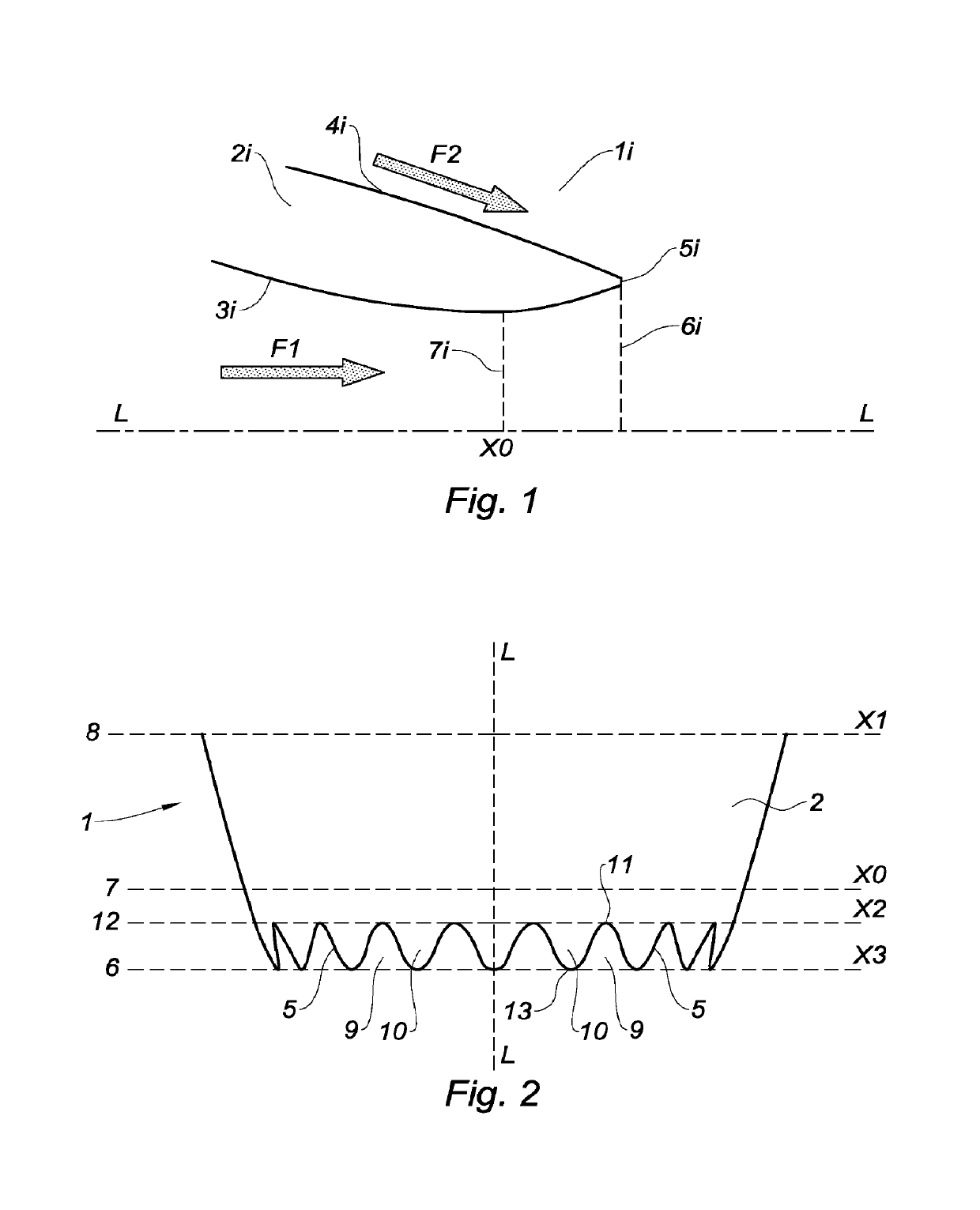
[0052]When the cowl does not surround a central body, the rotationally symmetric cross-section of the nozzle around an axis L-L is defined by a cross-section perpendicular to the axis L-L. The surface area of a cross-section is defined solely by the radius of the internal wall of the cowl in this plane. Since the walls of the cowl are of circular cross-section, they are convergent or divergent here if the radius decreases or increases respectively in the downstream direction.

[0053]FIG. 1 shows a known convergent-divergent reference nozzle 1i of a single-flow turbine engine. The reference nozzle 1i comprises an annular reference cowl 2i having a longitudinal axis L-L and a certain thickness which decreases close to its trailing edge 5i. The internal wall 3i of the cowl 2i defines a nozzle through which an internal gaseous flow F1 passes. The external wall 4i of this cowl 2i is in contact with an external gaseous flow F2.

[0054]The internal 3i and external...

second embodiment

NCE NOZZLE

[0108]In this variant, the reference nozzle 1i is simply convergent. An attempt will then be made to reduce the effect of supplementary convergence introduced by chevrons.

[0109]The cowl 2 of the nozzle obtained according to the present invention has, towards its trailing edge 5, a shape comprising chevrons 10 and indentations 9, which is defined by the same parameters as those of the first embodiment.

[0110]In this case there is no predefined neck, since the reference nozzle is convergent. A preliminary step therefore consists in choosing a cross-section 7, for an abscissa X0 on the axis L-L upstream of the outlet 6i of the reference nozzle 1i, on the basis of which the shape of the internal wall 3 of the cowl 2 of the optimised nozzle is modified. Once this abscissa X0 is determined, the construction of the surfaces defining the internal 3 and external 4 walls of the cowl 2 uses the same parameters and the same method as for the first embodiment.

[0111]The method for defini...

third embodiment

E NOZZLE

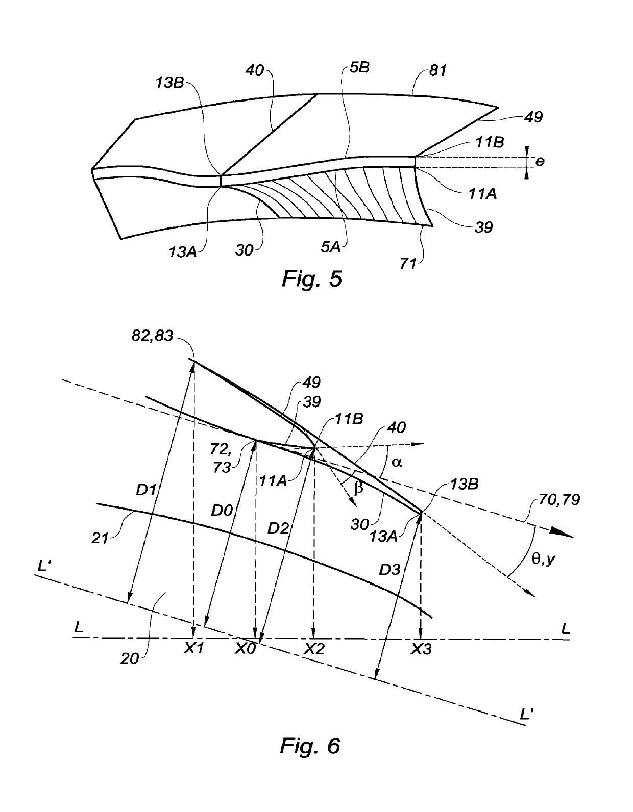
[0113]In the case of an exhaust nozzle for a double-flow turbojet engine for example, the nozzle corresponds to the air conduit defined between the internal wall of a cowl 2 and the wall 21 of a central body 20 of circular cross-section around the axis L-L shown in FIG. 6.

[0114]The cross-section of the nozzle is no longer defined by the radius of the internal face of the cowl 2. Known methods are used in this configuration and define, as the cross-section, a surface which is substantially perpendicular to the mean flow, which is no longer a plane perpendicular to the axis L-L. For example, the calculation method known as “rolling ball” consists in making a ball roll on one of the walls. When this ball touches the two walls, the line which joins the two points of contact defines the passage cross-section between these two points. By varying the diameter of the ball it is thus possible to define the passage cross-section over the length of the nozzle. Next, the convergent or d...


PUM


Abstract

A nozzle of a turbomachine is provided with chevrons with a non-axisymmetric inner face. A cover for the nozzle of longitudinal axis L-L includes an internal wall having a section with a predetermined abscissa on the L-L axis defining, on the wall, a neck line. The cover has, downstream from the abscissa, indentations in the trailing edge of the cover delimiting chevrons distributed in the circumferential direction, in which, on the cover, from the abscissa the internal wall moves away radially towards the outside of the upstream tangent, to the top of an indentation, the outer wall of the cover moves towards the upstream tangent to the top of an indentation, and the internal wall moves away radially towards the inside of the upstream tangent, to the tip of a chevron.

Description

TECHNICAL FIELD[0001]The present invention relates to the general field of reduction of the jet noise at the outlet of a turbine engine nozzle.[0002]In particular, the present invention concerns the definition of the shape of a turbine engine nozzle which has, at its downstream end, a trailing edge comprising chevrons in order to reduce the jet noise.PRIOR ART[0003]It is known that the jet at the outlet of a turbine engine nozzle encounters at least one other gaseous flow. Thus:[0004]when the turbine engine has a single flow, this flow comes into contact with the external air bypassing the nozzle; and[0005]when the turbine engine has a double flow, the primary flow (or hot flow) and the secondary flow (or cold flow) come into contact with one another, but also with the external air.[0006]The speed difference between the jet at the nozzle outlet and the other gaseous flow or flows which it encounters creates fluid shears penetrating between these gaseous flows, which causes noise, co...

Claims


Application Information

Patent Timeline
Patent Type & Authority Patents(United States)
IPC IPC(8): F02K1/44F02K1/46F02K1/38F02K1/34
CPCF02K1/44F02K1/34F02K1/386F02K1/46F05D2250/11F05D2260/96F05D2250/184F05D2250/323F05D2250/324F05D2250/711F05D2250/712F05D2250/183F02K1/38
Inventor LANGRIDGE, JONATHANSZYDLOWSKI, JULIEN
Owner SN DETUDE & DE CONSTR DE MOTEURS DAVIATION S N E C M A
Learn More