Vaginal irrigator

A technology of vaginal irrigation and irrigator, applied in the direction of enema/irrigator, syringe, infusion set, etc., can solve the problems of inconvenient force, awkward posture, failure to overcome the backflow of dirty liquid back to the bottle, etc., to achieve continuous flushing, prevent contamination Liquid backflow effect

Inactive Publication Date: 2007-05-09
上海瑞圣生物医学科技有限公司
View PDF5 Cites 3 Cited by
  • Summary
  • Abstract
  • Description
  • Claims
  • Application Information

AI Technical Summary

Problems solved by technology

First, a number of longitudinal grooves are arranged on the outer periphery of the nozzle tube, and the liquid spray holes are arranged in these grooves. When flushing, air can be filled into the bottle from the groove gap between the nozzle tube and the vaginal wall, so that continuous flushing can be carried out. , however, when the user is in a lying position, the direction of the nozzle tube is downward, and the flushing liquid cannot flow out smoothly, and stays in the longitudinal groove to block the spray hole, so that continuous cleaning cannot be performed. Moreover, the existence of the groove will cause The waste of flushing liquid; second, the bottle body is made into an accordion bellows shape, and the upper and lower ends of the bottle body are pinched t

Method used


Image

  • Vaginal irrigator
  • Vaginal irrigator
  • Vaginal irrigator

Examples


Embodiment Construction

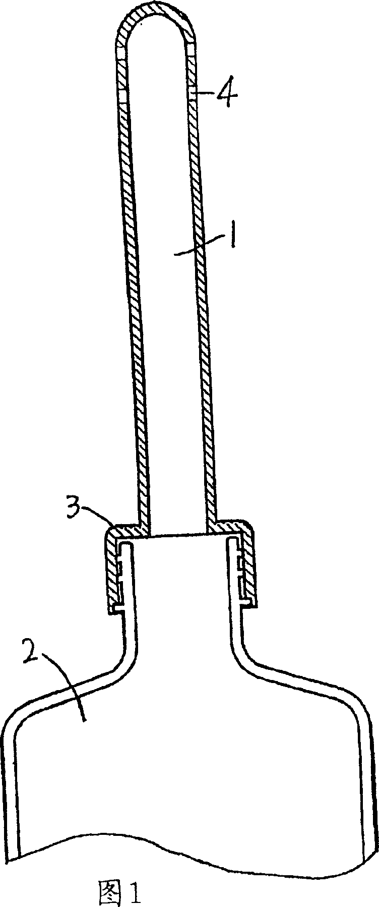
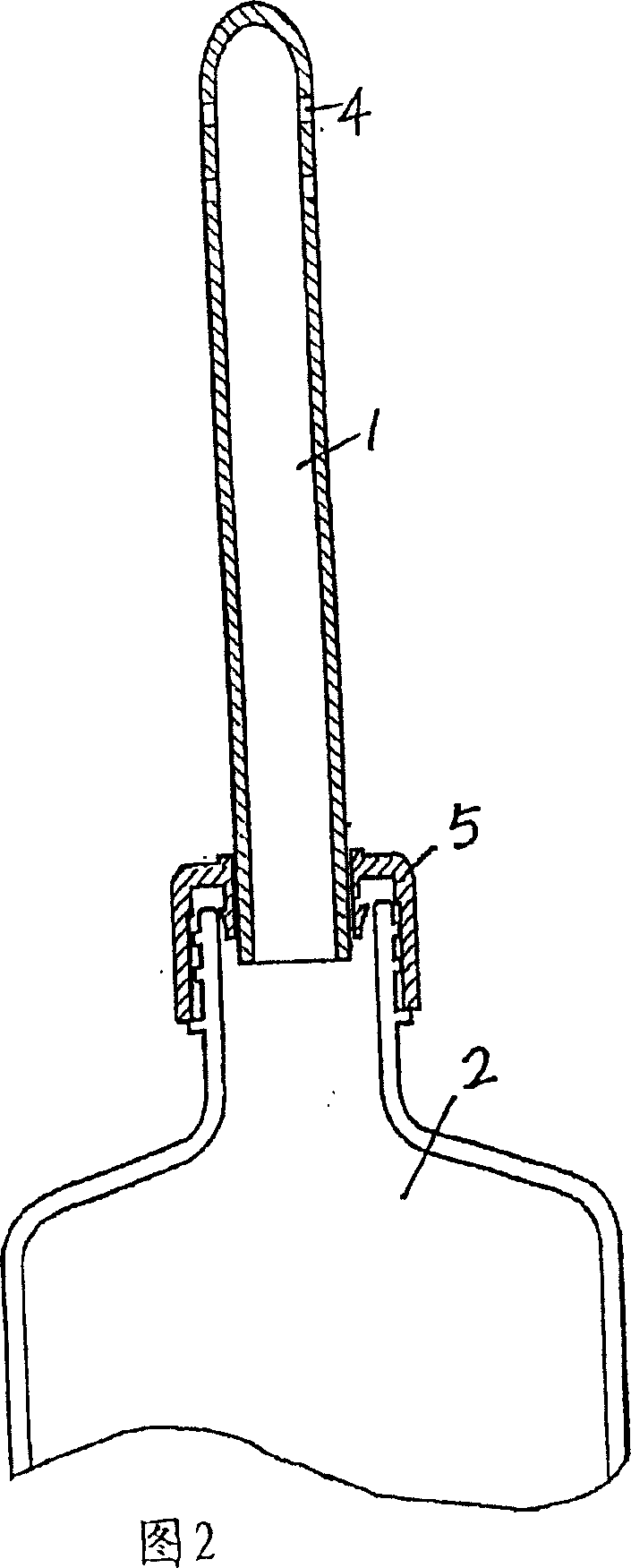
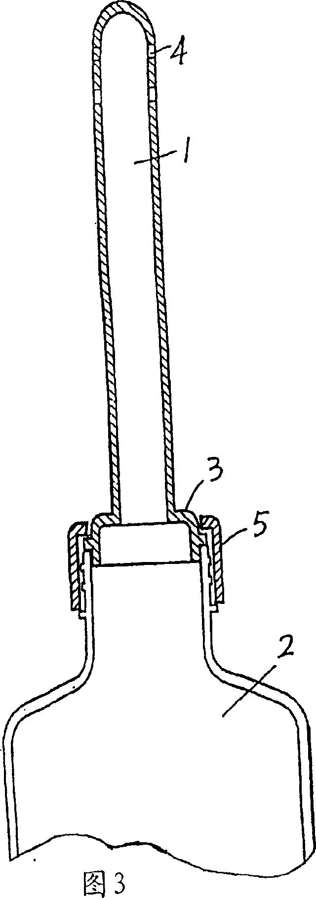
[0060] The vaginal irrigator shown in FIGS. 8 to 30 includes a nozzle tube 10, a bottle body 20, and a joint 30 connecting the nozzle tube and the bottle body. The joint section 30 is composed of a rear end 31 of the nozzle tube body and a connector 32. The nozzle The tube 10 and the bottle body 20 communicate with each other to form the inner cavity of the washer, and the joint 30 is provided with an air hole 40 for communicating the inner cavity of the washer and the external atmosphere. The air hole 40 can be arranged at the appropriate position of the rear end 31 of the nozzle tube body of the joint part 30 and the connecting piece 32 (including the two structures of the integral cover and the independent cover 33 of the rear end 31 of the nozzle tube 10), the air hole 40 and The combination of the membrane valve plate 50 can also be evolved in various ways, resulting in the following embodiments under the same concept.

[0061] The first embodiment shown in FIGS. 8 and 9 ...


PUM


Abstract

The present invention relates to a vagina irrigator which comprises a nozzle tube and a bottle. the nozzle tube is connected on the bottle. The irrigator comprises a unidirection vent valve which only allows outside air to enter the lumen of the irrigator when the irrigator is inserted into the vagina for the use. The irrigator also comprises a unidirection douche valve which can allow the gas and liqud inside the bottle to enter the lumen of the bottle when the irrigator is inserted into the vagina for the use. The irrigator also comprises a valve seat which is fixed at the back end of the nozzle tube. The unidirection vent valve comprises a vent hole, an air-intake passage which is inside the valve seat, and an air-intake valve plate which is fixed on the valve seat. The air-intake valve plate is limited to cover on the open which is on the approaching the lumen of the bottle side of the air-intake passage. The irrigator can continually irrigate and effectively prevent the dirty liquid from flowing backwards.

Description

technical field [0001] The present invention relates to women's personal hygiene and lavage treatment appliances, in particular to a vaginal douche. Background technique [0002] Ordinary vaginal irrigator, as shown in Figure 1, consists of a bottle body 2 containing cleaning solution and a nozzle tube 1 for introducing the cleaning solution into the vagina. The front part of the nozzle tube 1 is a tube body with a liquid spray hole 4. , the rear part of the nozzle tube 1 is a connecting piece 3 formed by the extension of the pipe body, and the connecting piece 3 is connected with the mouth of the bottle body with threads; For the connector 3 of the nozzle tube 1, the rear end of the tube body is inserted into the middle hole of the cover 5; some, as shown in Figure 3, the tube body is crimped on the bottle mouth with the cover 5; A vaginal douche in which the nozzle tube 5 can be retracted into the cavity 2 of the bottle body when not in use, as shown in Figure 5 is a vagi...

Claims


Application Information

Patent Timeline
IPC IPC(8): A61M3/02
CPCA61M3/0262A61M2210/1475A61M3/0279
Inventor 王晓明
Owner 上海瑞圣生物医学科技有限公司
Why Eureka
Try Eureka