Wireless communication device and transmission power control method

A wireless communication device and transmission power control technology, which is applied in the direction of wireless communication, power management, and selection devices, and can solve problems that have not yet been disclosed

Inactive Publication Date: 2001-12-19
PANASONIC CORP
View PDF0 Cites 2 Cited by
  • Summary
  • Abstract
  • Description
  • Claims
  • Application Information

AI Technical Summary

Problems solved by technology

[0008] In contrast, in a wireless communication system that performs asymmetric communication with a long time difference between transmission timing and reception timing, a method of controlling transmission power with high precision for each slot has not been disclosed so far.

Method used


Image

  • Wireless communication device and transmission power control method
  • Wireless communication device and transmission power control method
  • Wireless communication device and transmission power control method

Examples


Embodiment 1

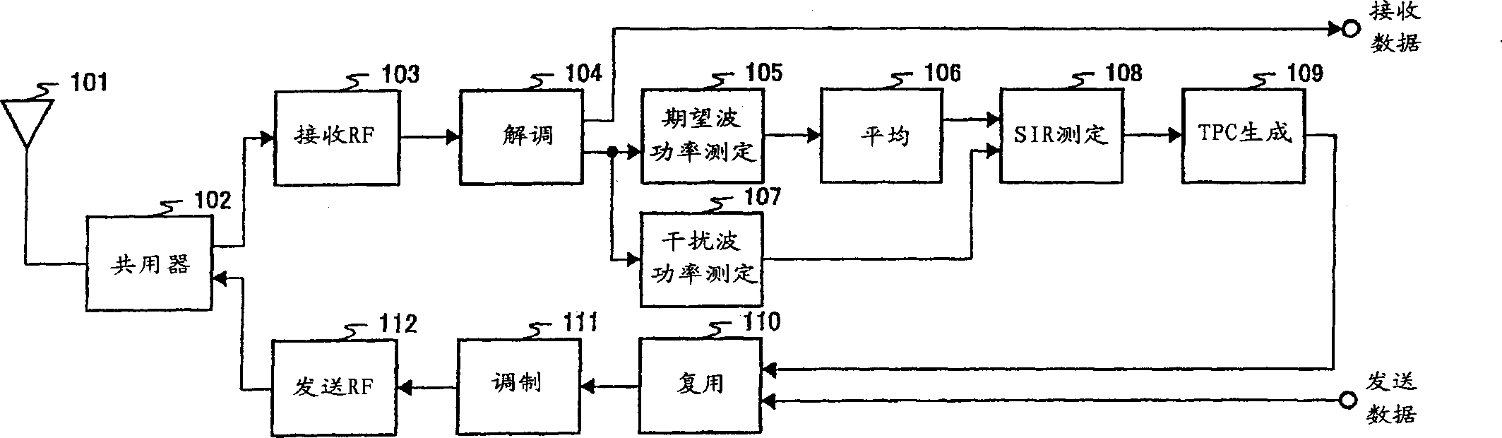
[0019] In Embodiment 1, the case of closed-loop transmission power control will be described. figure 1 It is a block diagram showing the structure of the wireless communication device according to Embodiment 1 of the present invention.

[0020] The duplexer 102 switches the path through which signals pass during transmission and reception, outputs the signal received from the antenna 101 to the reception RF circuit 103 , and outputs the transmission signal output from the transmission RF circuit 112 to the antenna 101 .

[0021] The receiving RF circuit 103 amplifies the received signal, converts the frequency to baseband, and outputs it to the demodulation circuit 104 . The demodulation circuit 104 demodulates the baseband signal, and extracts the received data of the own station.

[0022] The desired wave power measurement circuit 105 measures the received power of a known signal included in the output signal of the demodulation circuit 104 (hereinafter referred to as “desi...

Embodiment 2

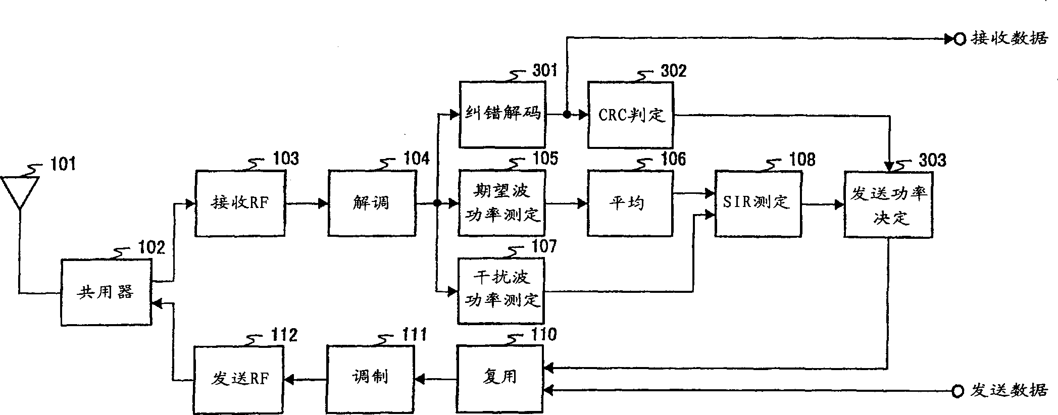
[0035] In Embodiment 2, a case of open-loop transmission power control including an outer loop (outer loop) for controlling transmission power control reference power will be described. image 3 It is a block diagram showing the structure of a wireless communication device according to Embodiment 2 of the present invention. exist image 3 In the wireless communication device shown, pair with figure 1 The components that operate in the same manner as the shown wireless communication device are appended with figure 1 The same reference numerals are used, and descriptions thereof are omitted.

[0036] image 3 The wireless communication device shown uses the figure 1 The configuration in which an error correction decoding circuit 301, a CRC determination circuit 302, and a transmission power determination circuit 303 are added to the wireless communication device shown is shown.

[0037] The error correction decoding circuit 301 performs error correction decoding processing ...


PUM


Abstract

The averaging circuit 106 averages the desired wave power measured by the desired wave power measuring circuit 105 within a plurality of time slots to reduce the power error of the desired wave power in each time slot. The SIR measurement circuit 108 calculates the SIR(n) of each time slot based on the average value of the desired wave power of a plurality of time slots and the measured value of the interference wave power of each time slot. The TPC generation circuit 109 calculates the SIR(n) of each time slot. ) and the threshold to generate transmit power control information. This enables highly accurate control of the transmission power for each time slot in asymmetric communication.

Description

technical field [0001] The present invention relates to a wireless communication device and a transmission power control method used in wireless transmission systems such as car phones and portable phones. Background technique [0002] In wireless transmission systems such as car phones and mobile phones, in order to keep SIR (Signal to Interference Ratio) constant and BER (Bit Error Rate) below a specified value, communication with each transmission line is performed. The state corresponds to the transmit power control. [0003] Among transmission power control methods, there are closed-loop transmission power control and open-loop transmission power control. [0004] Closed-loop transmission power control is a method of measuring the SIR relative to the reception quality of the own transmission signal at the communication counterpart, and transmitting it through the reverse line. When the measured SIR value is higher than the target SIR value, the transmission power is re...

Claims


Application Information

Patent Timeline
Patent Type & Authority Applications(China)
IPC IPC(8): H04L1/00H04B7/005H04B7/26H04J3/00H04W52/08H04W52/22H04W52/24
CPCH04W52/08H04W52/10H04W52/12H04W52/225H04W52/241H04W52/247H04W52/248
Inventor 平松胜彦
Owner PANASONIC CORP
Why Eureka
Try Eureka