Radio frequency signal detecting and positioning method

A technology of radio frequency signal detection and positioning method, which is applied in the direction of frequency measuring device, measuring device, measuring electric power, etc., to achieve the effects of reducing power error, improving frequency resolution, and reducing sampling time

Inactive Publication Date: 2020-06-26
佛山市联动科技股份有限公司
View PDF7 Cites 4 Cited by
  • Summary
  • Abstract
  • Description
  • Claims
  • Application Information

AI Technical Summary

Problems solved by technology

[0006] The purpose of the present invention is to provide a radio frequency signal detection and positioning method to solve one or more technical problems in the prior art, at least provide a beneficial option or create conditions

Method used


Image

  • Radio frequency signal detecting and positioning method
  • Radio frequency signal detecting and positioning method
  • Radio frequency signal detecting and positioning method

Examples


Embodiment Construction

[0047] The idea, specific structure and technical effects of the present invention will be clearly and completely described below in conjunction with the embodiments and accompanying drawings, so as to fully understand the purpose, scheme and effect of the present invention. It should be noted that, in the case of no conflict, the embodiments in the present application and the features in the embodiments can be combined with each other.

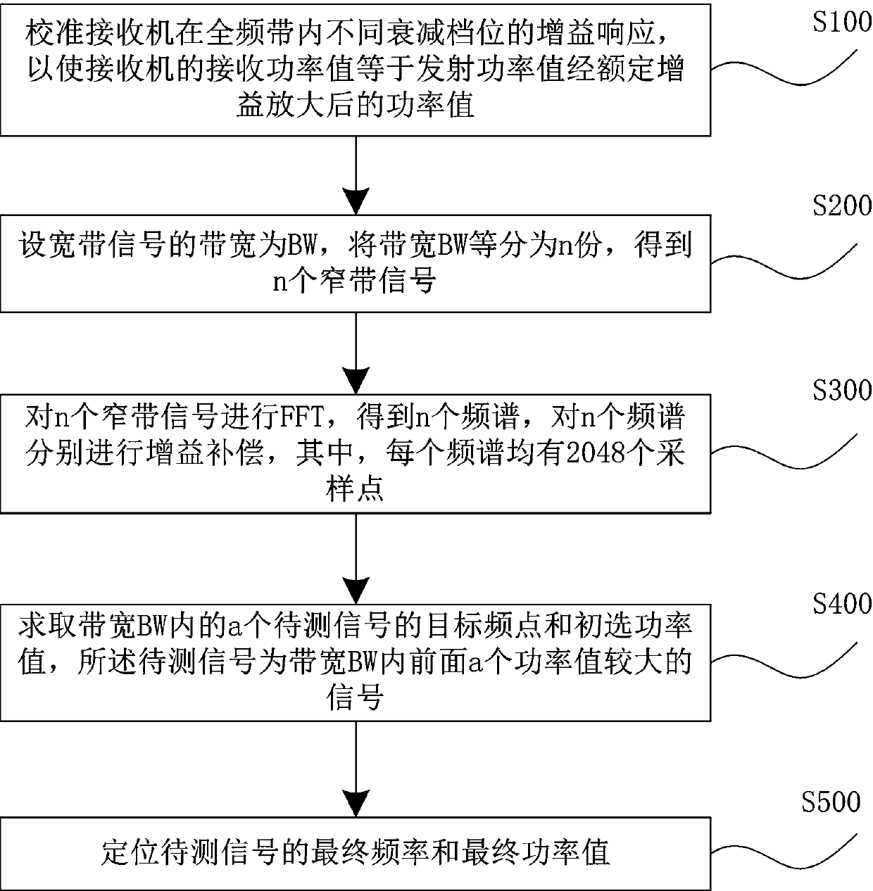
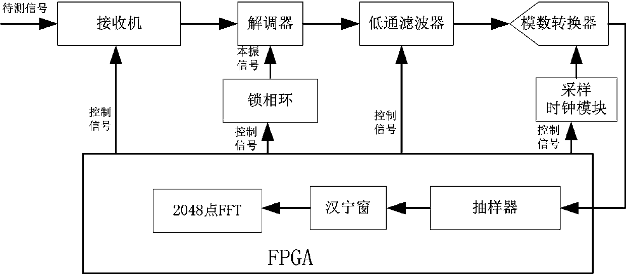
[0048] refer to figure 1 and figure 2 , the embodiment of the present invention provides a radio frequency signal detection and positioning method, which is applied to a radio frequency signal detection and positioning system, and the radio frequency signal detection and positioning system includes an FPGA (Field Programmable Gate Array, Field Programmable Logic Gate Array), a receiver, a demodulator device, phase-locked loop, low-pass filter, sampling clock module and analog-to-digital converter, the FPGA is connected to the receiver and t...


PUM


Abstract

The invention relates to the technical field of computer data processing, in particular to a radio frequency signal detecting and positioning method, which comprises the following steps of: firstly, calibrating gain responses of a receiver at different attenuation gears in a full frequency band so as to enable a receiving power value of the receiver to be equal to a power value of a transmitting power value after rated gain amplification; equally dividing the bandwidth into narrow-band signals, performing FFT on the narrow-band signals, and performing gain compensation on the obtained frequency spectrum; further solving a target frequency and a primary power value of a to-be-measured signal in the bandwidth, and determining a final frequency and a final power value of the to-be-measured signal. According to the method, the frequency and the power of the signals of any order and any frequency band in the bandwidth can be detected and positioned.

Description

technical field [0001] The invention relates to the technical field of computer data processing, in particular to a radio frequency signal detection and positioning method. Background technique [0002] In the field of radio frequency testing, especially in the field of communication and in the design of phase-locked loops, it is very important to test useful signals and spurious signals. In the field of communication, spurs outside the occupied frequency band will occupy other communication channels and cause damage to other channel signals. Interference reduces the sensitivity of other channels, and the frequency offset and power offset of the useful signal will also affect the quality of the channel signal; therefore, it is of great significance to accurately test the signal. [0003] In radio frequency testing, in order to accurately detect and locate the signal, it is necessary to detect and locate the frequency and power of any order and any frequency band signal withi...

Claims


Application Information

Patent Timeline
Patent Type & Authority Applications(China)
IPC IPC(8): G01R23/02G01R21/00H04B17/29
CPCG01R21/00G01R23/02H04B17/29
Inventor 刘旭伟
Owner 佛山市联动科技股份有限公司
Why Eureka
Try Eureka