Fuel feeding apparatus

A fuel supply device and fuel technology, applied in fuel injection devices, liquid fuel feeders, low-pressure fuel injection, etc., can solve problems such as difficulty in maintaining pump performance, unbalanced pump discharge, etc., to achieve suppression of steam generation, good The effect of maintaining and improving connection workability

Inactive Publication Date: 2007-08-08
KEIHIN CORP
View PDF4 Cites 0 Cited by
  • Summary
  • Abstract
  • Description
  • Claims
  • Application Information

AI Technical Summary

Problems solved by technology

[0013] According to the above description, due to the compression of the steam in the plunger pump, the pump discharge is prone to imbalance, and it is difficult to maintain stable pump performance.

Method used


Image

  • Fuel feeding apparatus
  • Fuel feeding apparatus
  • Fuel feeding apparatus

Examples


Embodiment Construction

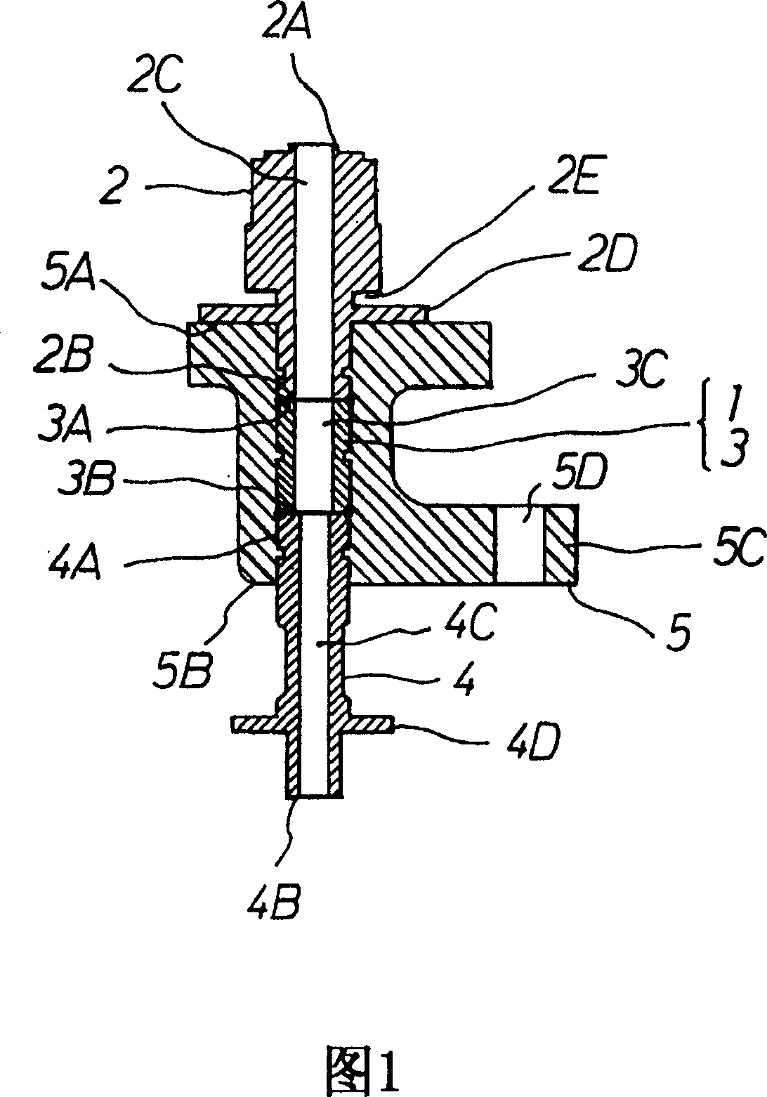
[0037] An embodiment of the fuel supply device of the present invention will be described below with reference to FIG. 1 .

[0038] 1 denotes a pipe assembly, and the pipe assembly 1 is formed of a pump stationary core 2, a tubular member 3, and an injection valve stationary iron core 4, and is formed as follows.

[0039] The pump fixed core 2 is made of magnetic material, the fuel discharge passage 2C is opened from the upper end 2A to the lower end 2B in a penetrating manner, and an engaging flange portion 2D and an engaging groove 2E are formed in the middle of its outer periphery.

[0040] The annular member 3 is formed of a non-magnetic material, and a fuel flow path 3C is formed penetratingly from the upper end 3A toward the lower end 3B.

[0041] The injection valve fixed core 4 is formed of a magnetic material, the fuel inflow passage 4C is opened from the upper end 4A to the lower end 4B in a penetrating manner, and an annular flange portion 4D serving as an upper mag...


PUM


Abstract

In order to accurately supply fuel with using an electromagnetic fuel injection valve (J), improve a mounting property of a fuel supply apparatus to an engine and simplify fuel piping, a pipe assembly (1) outward molded in a base body (5) is formed by connecting a fixed iron core for a pump (2) made of a magnetic material, a tubular member (3) made of a nonmagnetic material, and a fixed iron core for an injection valve (4) made of a magnetic material, a fuel discharge passage (2C) of the fixed iron core for pump, a fuel flow passage (3C) of the tubular member (3) and a fuel inflow passage (4C) of the fixed iron core for injection valve (4) are connected in an airtight manner, an electromagnetic fuel pump (P) is connected to the fixed iron core for pump (2) protruding to one side from the base body (5), and the injection valve (J) is connected to the fixed iron core for injection valve (4) protruding the other side from the base body (5).

Description

technical field [0001] The present invention relates to a fuel injection device. In the fuel injection device, the pressure of the fuel stored in the fuel tank is increased by the fuel pump, and the fuel with the increased pressure is injected into the engine through the fuel injection valve, wherein , the present invention particularly relates to a fuel supply device composed of a fuel pump and a fuel injection valve. Background technique [0002] A conventional fuel supply device is disclosed in JP-A-2001-221137. Among them, in particular, FIG. 8 discloses the following. [0003] That is, the plunger pump and the nozzle are arranged integrally connected, the spacer is fixedly arranged by riveting at the lower end of the pump body constituting the plunger pump, and the upper part of the nozzle cylinder is screwed to the spacer. [0004] In addition, the nozzles include an orifice nozzle that passes fuel whose pressure rises in the latter part of the pressure-feeding strok...

Claims


Application Information

Patent Timeline
Patent Type & Authority Patents(China)
IPC IPC(8): F02M69/00F02M55/02F02M37/00F02M37/06F02M37/10F02M51/06
CPCY02T10/123Y02T10/12
Inventor 佐藤健一堀篭胜博宫野征雄
Owner KEIHIN CORP
Why Eureka
Try Eureka