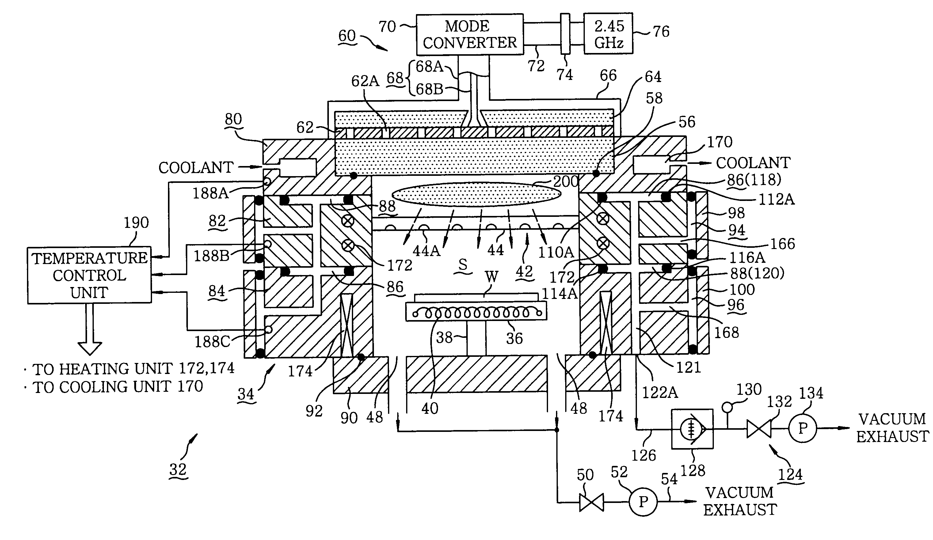
Processing apparatus
a technology of processing apparatus and processing vessel, which is applied in the direction of coating, chemical vapor deposition coating, electric discharge tube, etc., can solve the problems of high probability, difficult to remove unnecessary film adhering thereto at a low temperature, and high temperature, so as to improve the energy efficiency involved in heating and/or cooling the processing vessel
- Summary
- Abstract
- Description
- Claims
- Application Information
AI Technical Summary
Benefits of technology
Problems solved by technology
Method used
Image

Examples
first modified embodiment
[0068](First Modified Embodiment)
[0069]Although the middle block body 82 is formed of a single piece in the foregoing embodiment, it may be possible to fabricate the middle block body 82 from a plurality of, e.g., three, mutually layered pieces 82A, 82B and 82C as illustrated in FIG. 7. In this case, seal members 202 such as O-rings or the like are provided between the adjoining pieces 82A, 82B and 82C to seal off the gaps between the pieces. The adjoining pieces 82A, 82B and 82C are brought into metal-to-metal contact with one another to assure good heat transferability between the pieces. Shield members for preventing leakage of the microwaves may be interposed between the adjoining pieces as is the case in the foregoing embodiment. If the middle block body 82 is constructed by combining the plurality of pieces together, it becomes possible to endow each of the pieces with a special function. As an example, a gas ring structure for supplying a cleaning gas may be provided by formi...
second modified embodiment
[0070](Second Modified Embodiment)
[0071]In the event that the interior of the processing vessel 34 is subjected to, e.g., maintenance and repair in the processing apparatus described above and illustrated in FIGS. 1 to 7, the ceiling plate 56 is separated together with the upper block body 80 provided in the ceiling portion of the processing vessel 34 to thereby open the processing vessel 34 and, then, an operator is allowed to perform a maintenance and repair operation within the processing vessel 34.
[0072]However, since the shower head 44 is fixedly secured to the middle block body 82 in this case, it is quite difficult to conduct the maintenance and repair operation. Further, the maintenance and repair operation becomes highly onerous because the shower head 44 needs to be removed depending on the circumstances. Moreover, a cumbersome operation of adjusting the gaps of the heat insulating gaps present between the upper block body 80 and the middle block body 82 needs to be perfor...
PUM
| Property | Measurement | Unit |
|---|---|---|
| thickness | aaaaa | aaaaa |
| temperature | aaaaa | aaaaa |
| temperature | aaaaa | aaaaa |
Abstract
Description
Claims
Application Information
 - R&D Engineer
- R&D Manager
- IP Professional
- Industry Leading Data Capabilities
- Powerful AI technology
- Patent DNA Extraction
Browse by: Latest US Patents, China's latest patents, Technical Efficacy Thesaurus, Application Domain, Technology Topic.
© 2024 PatSnap. All rights reserved.Legal|Privacy policy|Modern Slavery Act Transparency Statement|Sitemap