Latent heat absorbing apparatus for gas boiler

A gas-fired boiler and latent heat technology, applied in air heaters, water heaters, fluid heaters, etc., can solve problems such as difficult assembly and high manufacturing costs

Inactive Publication Date: 2005-04-13
TAISEI SANGYO
View PDF0 Cites 8 Cited by
  • Summary
  • Abstract
  • Description
  • Claims
  • Application Information

AI Technical Summary

Problems solved by technology

However, in the above-mentioned system, since each part of the sensible heat exchanger and the latent heat exchanger is directly exposed to the

Method used


Image

  • Latent heat absorbing apparatus for gas boiler
  • Latent heat absorbing apparatus for gas boiler
  • Latent heat absorbing apparatus for gas boiler

Examples


Embodiment Construction

[0019] Some preferred embodiments of the present invention will be described in detail below with reference to the accompanying drawings.

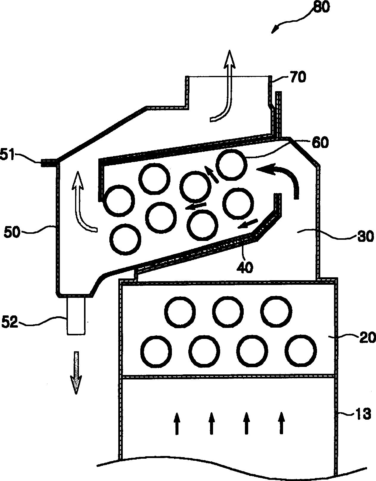
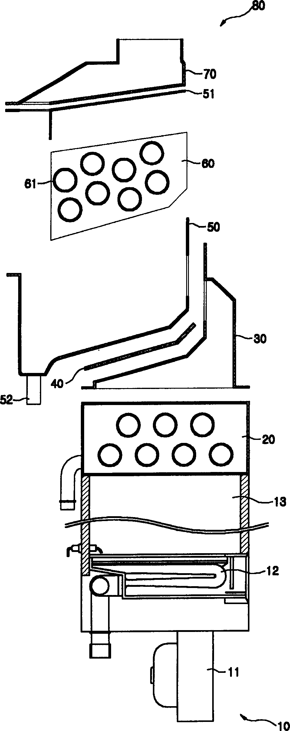
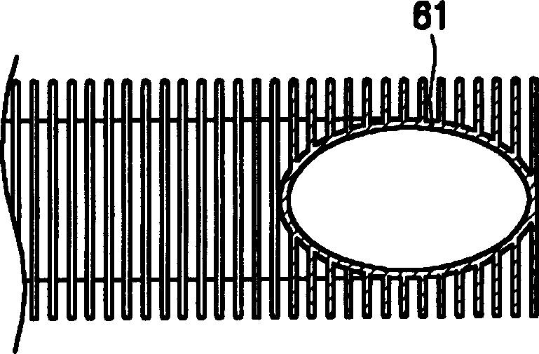
[0020] figure 1 shows a latent heat absorber 80 according to the invention, figure 2 Shown is a gas boiler 10 provided with a latent heat absorber 80 of the present invention. image 3 and Figure 4 Conduits 61 and 62 of latent heat absorber 80 of the present invention are shown.

[0021] According to the present invention, the latent heat absorbing device 80 is installed above the combustion chamber 13 of the gas boiler 10 .

[0022] In addition to the combustion chamber 13 , the gas boiler 10 also includes a blower 11 , a burner 12 , a sensible heat exchanger 20 and a first passage 30 .

[0023] The blower 11 is installed below the lowermost portion of the gas boiler 10 . The blower 11 includes a motor and a blower fan. The motor is rotated by supplying electric power to the motor from the outside. Under the action of the rotatin...


PUM


Abstract

The invention discloses a latent heat absorbing device for a gas boiler. Said gas boiler comprises a latent heat exchanger installed in the chamber such that the latent heat exchanger is separated from the sensible heat exchanger and also separated from the exterior of the gas boiler. The invention prevents heat transfer between the heat exchangers and also prevents condensate from dripping onto the elements of the gas boiler. In addition, at the first channel communicating with both the combustion chamber and the chamber above, the exhaust gas can also maintain a smooth flow in an accelerated state.

Description

technical field [0001] The present invention relates to a gas-fired boiler employing an upward-type Bunsen burner combustion system, and more particularly to a latent heat absorbing device for a gas-fired boiler, which utilizes a latent heat exchanger to recover waste heat , so as to improve thermal efficiency and reduce gas consumption, the waste heat is usually generated after heat exchange with hot water flowing through the sensible heat exchanger, and then the waste heat is discharged together with the exhaust gas. Background technique [0002] In general, a gas boiler is constructed such that the heat of exhaust gas generated after combustion of fuel such as gas and the heat of water such as hot water are exchanged in a heat exchanger located on the combustion chamber, thereby enabling Room or water for heating. [0003] After the gas is burned in the gas boiler, the generated combustion gas is used for heat exchange through a heat exchanger, and then the combustion ge...

Claims


Application Information

Patent Timeline
IPC IPC(8): F24H1/40F24H8/00
CPCF24H1/40F24H8/00F24H8/006F28F1/02F28F1/26Y02B30/00F24H1/14
Inventor 流炫旭
Owner TAISEI SANGYO
Why Eureka
Try Eureka