Liquid crystal display

A technology of liquid crystal display device and laser light source, applied in lighting devices, cooling/heating devices of lighting devices, optics, etc., can solve problems such as radiator 27 not being installed

Inactive Publication Date: 2015-04-01
MITSUBISHI ELECTRIC CORP
View PDF4 Cites 8 Cited by
  • Summary
  • Abstract
  • Description
  • Claims
  • Application Information

AI Technical Summary

Problems solved by technology

In addition, the heat sink 27 is not mounted on the part

Method used


Image

  • Liquid crystal display
  • Liquid crystal display
  • Liquid crystal display

Examples


Embodiment approach 1

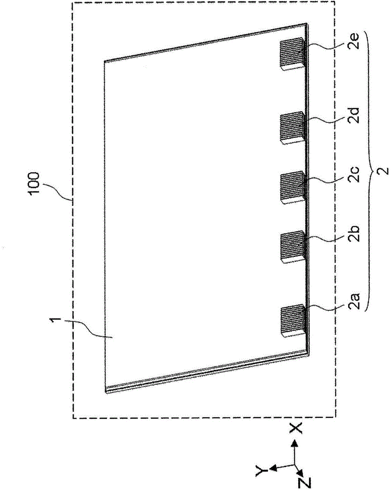
[0027] Hereinafter, in order to facilitate description of the drawings, the coordinate axes of the XYZ rectangular coordinate system are shown in each drawing. Let the short-side direction of the liquid crystal display device 100 be the Y-axis direction, let the long-side direction be the X-axis direction, and let the direction perpendicular to the X-Y plane be the Z-axis direction. Let the display surface side of the liquid crystal display device 100 be the +Z axis direction. In addition, the upward direction of the liquid crystal display device is defined as the +Y-axis direction. Looking at the display surface of the liquid crystal display device 100 , let the left side be the +X-axis direction. "Observing the display surface" means facing the display surface.

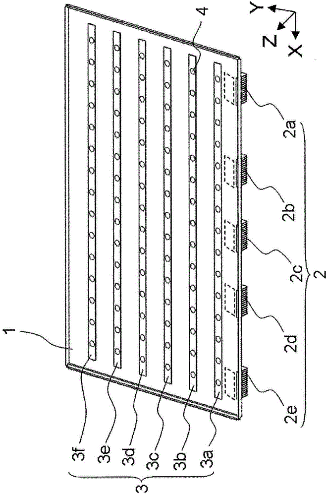
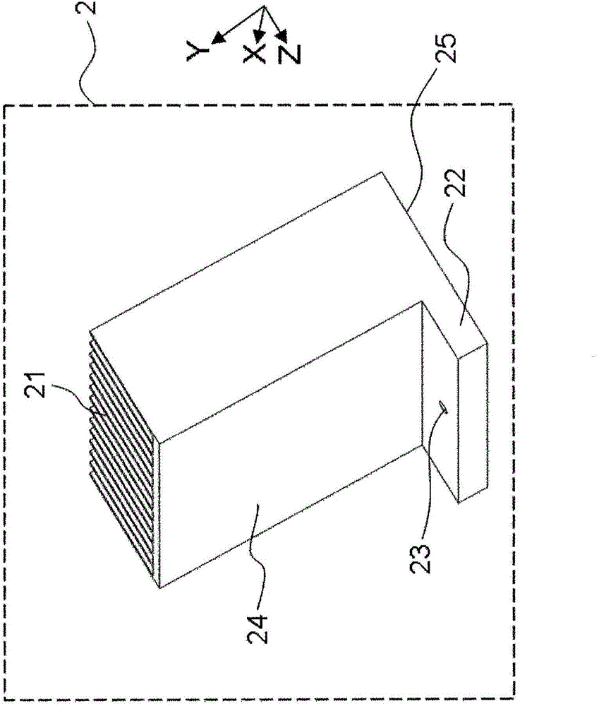
[0028] figure 1 It is a rear perspective view of the liquid crystal display device 100 according to Embodiment 1 of the present invention. The rear portion 1 is a holding member disposed on the rear side of the...

Embodiment approach 2

[0077] Figure 7 It is a rear perspective view of the liquid crystal display device 101 according to Embodiment 2 of the present invention. and figure 1 The liquid crystal display device 100 of Embodiment 1 shown is different in that the heat dissipation of the heat sinks 2b, 2c, and 2d arranged inside the heat sinks 2a, 2b, 2c, 2d, and 2e in the horizontal direction (X-axis direction) is different. The area is larger than the heat radiation area of ​​the heat sinks 2a and 2e arranged outside in the horizontal direction.

[0078]Other than the above point, it is the same as Embodiment 1. That is, the back part 1, the heat insulating part 15, the LED light source array 3, the LED light source 4, the laser light source 5, the reflection part 8, the reflection sheet 9, the light guide rod 10, the diffuser plate 11, the optical sheet 12, the liquid crystal display element 13 and the heat dissipation The structure other than the heat dissipation area of ​​the device 2 is the sa...


PUM


Abstract

A liquid crystal display (100) is provided with a laser light source (5), an LED light source (4), and a radiator (2). The laser light source (5) emits laser light (51). The LED light source (4) emits LED light (41). The radiator (2) holds the laser light source (5), and transmits heat produced by the laser light source (5) and releases said heat in the air. The laser light source (5) is positioned lower than the LED light source (4). The liquid crystal display (100) prevents heat from the LED light source (4), which is not easily affected by heat, from being transferred to the laser light source (5), which is easily affected by heat.

Description

technical field [0001] The present invention relates to a cooling structure of a liquid crystal display device having two types of light sources. Background technique [0002] The liquid crystal display element itself included in the liquid crystal display device does not emit light. Therefore, the liquid crystal display device includes a backlight device on the back of the liquid crystal display element as a light source for illuminating the liquid crystal display element. The liquid crystal display element receives light emitted from the backlight device and emits image light. In recent years, with the dramatic improvement in performance of blue light emitting diodes (hereinafter referred to as LEDs (Light Emitting Diodes)), backlight devices using blue LEDs as light sources have been widely used. [0003] The light source using the blue LED has, as constituent elements, a blue LED element and a phosphor that absorbs light emitted from the blue LED element and emits ligh...

Claims


Application Information

Patent Timeline
IPC IPC(8): F21S2/00F21V29/503F21V29/15G02F1/1333G02F1/13357F21Y101/02
CPCG02F1/133603G02F1/133615G02F1/133621G02F1/133628
Inventor 长濑章裕永安哲也新仓荣二
Owner MITSUBISHI ELECTRIC CORP
Why Eureka
Try Eureka