Rotary compressor

a compressor and rotary technology, applied in the direction of machines/engines, liquid fuel engines, positive displacement liquid engines, etc., can solve the problems of degrading the compression efficiency, and achieve the effect of improving the strength of the end plate member and improving the compression efficiency

Active Publication Date: 2010-09-09
DAIKIN IND LTD
View PDF20 Cites 8 Cited by
  • Summary
  • Abstract
  • Description
  • Claims
  • Application Information

AI Technical Summary

Benefits of technology

[0020]In the rotary compressor of this embodiment, since the barriers are formed integrally with the end plate member so as to couple the body portion and the boss portion to each other, the barriers function as ribs, so that the strength of the end plate member can be improved.
[0021]According to the rotary compressor of the present invention, the stagnation space of the muffler chamber ov

Problems solved by technology

It has been the case, therefore, that from the refrigerant gas discharged from the cylinder chamber, heat

Method used


Image

  • Rotary compressor
  • Rotary compressor
  • Rotary compressor

Examples


Embodiment Construction

[0026]Hereinbelow, the present invention will be described in detail by way of embodiments thereof illustrated in the accompanying drawings.

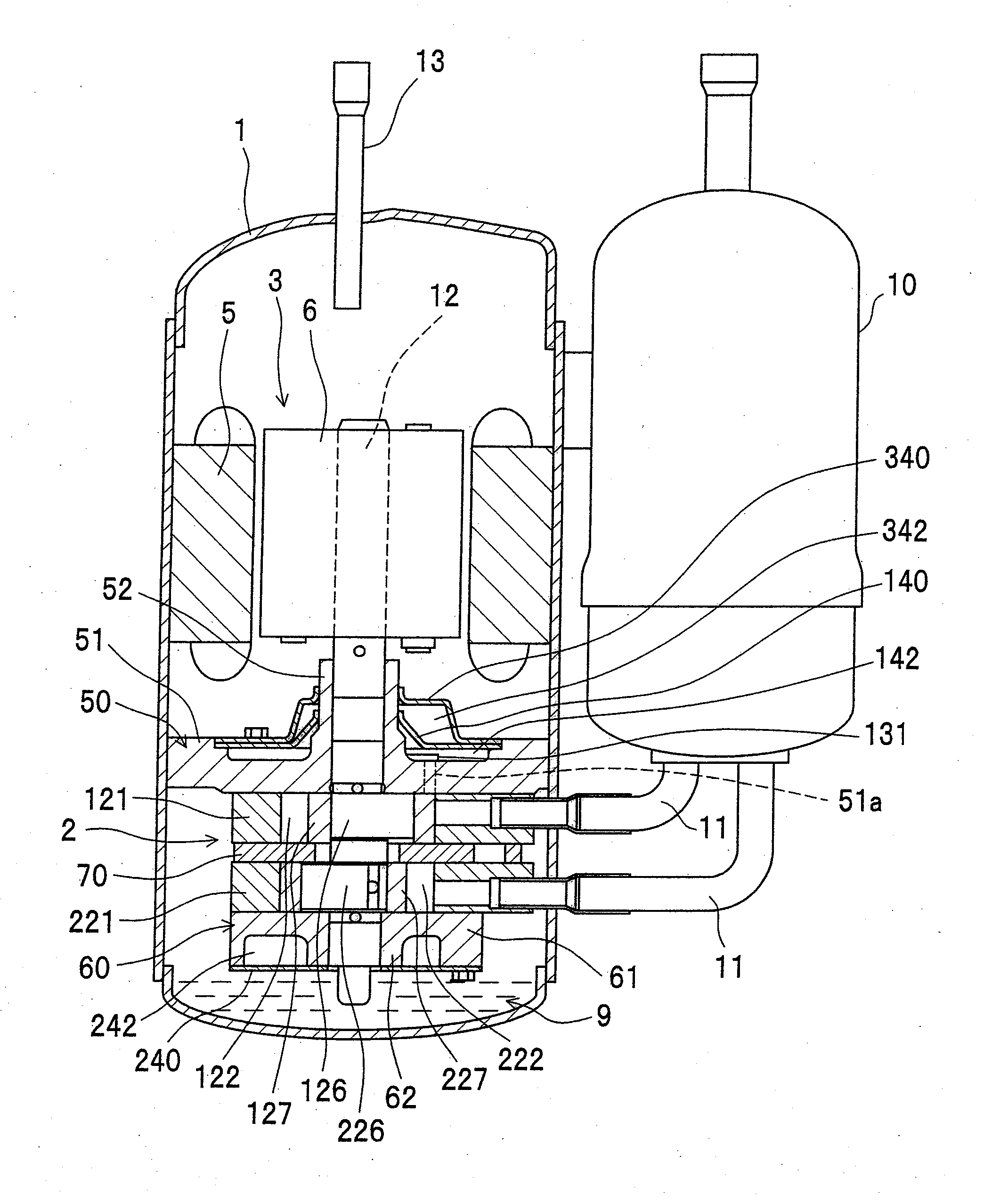
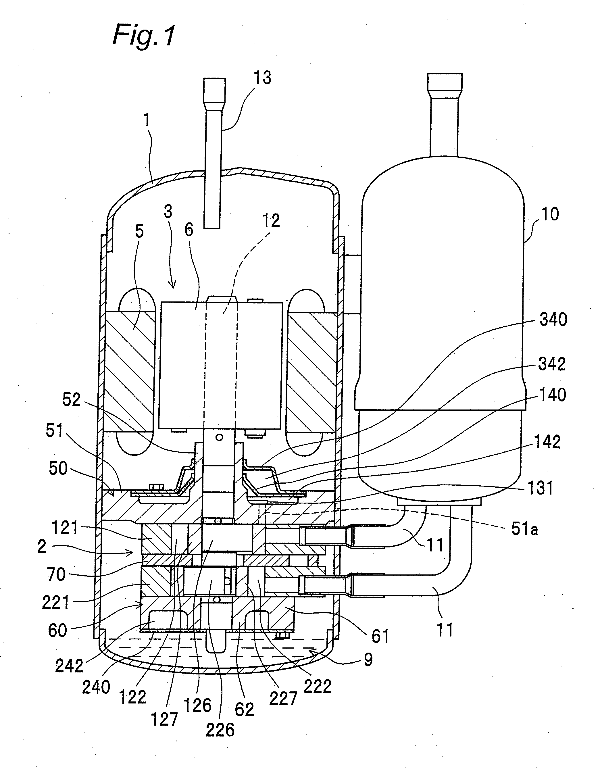
[0027]FIG. 1 is a longitudinal sectional view showing an embodiment of the rotary compressor of the invention. This rotary compressor includes a closed container 1, a compression element 2 placed within the closed container 1, and a motor 3 which is placed within the closed container 1 and which drives the compression element 2 via a shaft 12. The rotary compressor, which is the so-called high-pressure dome type, has the compression element 2 placed lower and the motor 3 placed upper within the closed container 1.

[0028]The motor 3 has a rotor 6, and a stator 5 placed radially outside the rotor 6 with an air gap placed therebetween. The shaft 12 is fitted to the rotor 6.

[0029]The rotor 6 has a rotor body formed of, for example, a laminated electromagnetic steel sheet, and a magnet buried in the rotor body. The stator 5 has a stator body formed of...


PUM


Abstract

A stagnation space defined by barriers is provided in a first muffler chamber communicating with a first cylinder chamber. The stagnation space overlaps with a refrigerant-gas inlet side of the first cylinder chamber, the inlet side being bordered by a center plane as viewed in a direction of a center axis of the first cylinder chamber. In the first muffler chamber, the high-temperature, high-pressure refrigerant gas is unlikely to enter into the stagnation space, so that heat is less absorbed to the inlet side of the first cylinder chamber.

Description

TECHNICAL FIELD[0001]The present invention relates to a rotary compressor to be used for, for example, air conditioners, refrigerators or the like.BACKGROUND ART[0002]Conventionally, there has been provided a rotary compressor which includes a cylinder, an end plate member attached to an opening end of the cylinder, a muffler cover attached to one side of the end plate member opposite to another side to which the cylinder is attached, and a roller for partitioning a cylinder chamber defined by the cylinder and the end plate member into a refrigerant-gas inlet chamber and a refrigerant-gas discharge chamber (see JP H9-151888 A).DISCLOSURE OF THE INVENTION[0003]However, in the above conventional rotary compressor, a high-temperature refrigerant gas discharged from the cylinder chamber, when passing through a muffler chamber defined by the muffler cover and the end plate member, passes through a space overlapping with the low-temperature, low-pressure inlet chamber of the cylinder cham...

Claims


Application Information

Patent Timeline
IPC IPC(8): F04B39/00
CPCF01C21/108F04C18/322F04C29/065F04C23/008F04C29/04F04C23/001F04C29/06F04C18/32
Inventor KANAYAMA, TAKEHIROMORIMOTO, KOUKIYANAGISAWA, MASANORI
Owner DAIKIN IND LTD
Why Eureka
Try Eureka