Heating cooking appliance
a technology for cooking appliances and cooking pots, applied in the field of heating cooking pots, can solve the problems of easy damage or malfunction of the control unit, and achieve the effect of preventing further damage and malfunctioning of the control uni
- Summary
- Abstract
- Description
- Claims
- Application Information
AI Technical Summary
Benefits of technology
Problems solved by technology
Method used
Image

Examples
first embodiment
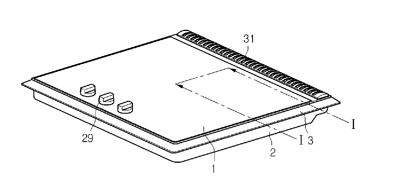
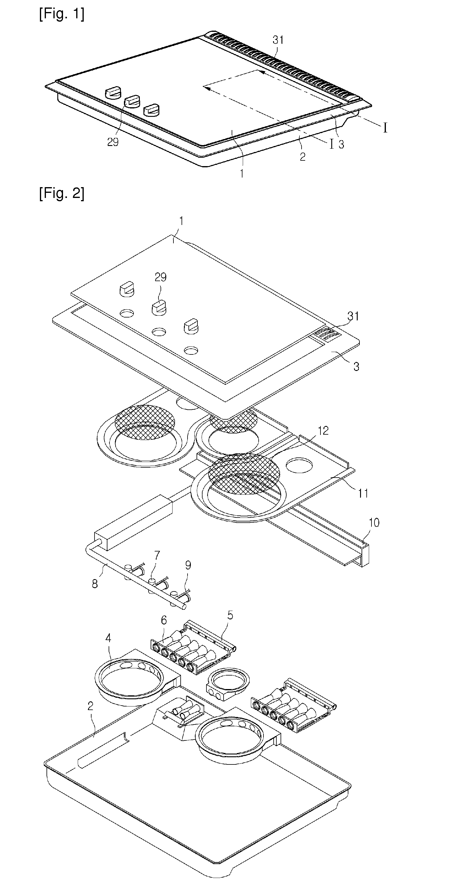
[0023]FIG. 1 is a perspective view of a heating cooking appliance according a first embodiment of the present disclosure and FIG. 2 is an exploded perspective view of the heating cooking appliance of FIG. 1.
[0024]Referring to FIGS. 1 and 2, a heating cooking appliance of a first embodiment includes a case 2 defining a lower appearance of the heating cooking appliance and having an opened top, a ceramic plate 1 seating on a top of the case 2, and a top plate 3 covering an edge of the ceramic plate 1.
[0025]The heating cooking appliance an exhaust grill 31 that is formed on a rear portion of the heating cooking appliance to exhaust combusted gas and a switch 29 that is formed on a front portion of the ceramic plate 1 to control an on / off of the gas combustion.
[0026]The locations and structures of the exhaust grill 31 and the switch 29 may be varied. However, it will be understood that an exhaust portion for exhausting the combusted gas and a switch portion for controlling the on / off of...
second embodiment
[0133]A second embodiment is identical to the first embodiment except for a structure of the spark plug. Therefore, like parts will not be described in detail in the second embodiment.
[0134]FIG. 13 is a view of a spark plug according to a second embodiment.
[0135]Referring to FIG. 13, according to a feature of this second embodiment, a heat detecting rod 28 functions as an ignition rod of the spark plug 26.
[0136]In more detail, an ignition rod 27 protrudes toward the burner frame and a thermal detecting rod 27 for detecting a temperature of the glow plate 12 protrudes to a location spaced apart from the ignition rod 26.
[0137]When the current is applied to the ignition rod 27, the spark plug 26 ignites the mixture gas by generating sparks between the thermal detecting rod 28 and the ignition rod 27.
[0138]The thermal ignition rod 28 is inserted in the burner frame 11 and extends to an external side of the burner frame 11. A support 23 supporting a thermostat 24 is installed on an exten...
third embodiment
[0140]A third embodiment is identical to the first embodiment except for a structure of the heating elements. Therefore, like parts will not be described in detail in the third embodiment.
[0141]FIG. 14 is a perspective view of a sub-heating unit according to a third embodiment.
[0142]Referring to FIG. 14, a heating element 356 is formed in a coil shape and coupled to the supporting member 352. The, coil-shaped heating element 356 is coupled to the supporting member 352 while having predetermined elastic force.
[0143]Therefore, after the heating elements 356 are heated, the heating elements 356 is not drooped but horizontally tensioned, thereby not contacting the glow plate 12.
[0144]The heating element is formed in a coil shape to have the elastic force in this embodiment. However, the catching portions of the supporting member, to which the heating elements are coupled, may be designed having elastic force.
PUM
 Abstract
Description
Claims
Application Information
 - R&D Engineer
- R&D Manager
- IP Professional
- Industry Leading Data Capabilities
- Powerful AI technology
- Patent DNA Extraction
Browse by: Latest US Patents, China's latest patents, Technical Efficacy Thesaurus, Application Domain, Technology Topic.
© 2024 PatSnap. All rights reserved.Legal|Privacy policy|Modern Slavery Act Transparency Statement|Sitemap