Eureka AIR delivers breakthrough ideas for toughest innovation challenges, trusted by R&D personnel around the world.

Double-optical fibre circular cascade laser warning device

A laser warning and dual-fiber technology, applied in the field of optoelectronics, can solve the problems of reducing system accuracy and reducing the number of optical windows

Inactive Publication Date: 2007-08-15
UNIV OF ELECTRONICS SCI & TECH OF CHINA
View PDF4 Cites 0 Cited by
  • Summary
  • Abstract
  • Description
  • Claims
  • Application Information

AI Technical Summary

Problems solved by technology

Although increasing the interval between the characteristic frequencies of adjacent optical antennas can reduce the influence of crosstalk, it reduces the number of optical windows and reduces the accuracy of the system.

Method used


Image

  • Double-optical fibre circular cascade laser warning device
  • Double-optical fibre circular cascade laser warning device
  • Double-optical fibre circular cascade laser warning device

Examples


Embodiment Construction

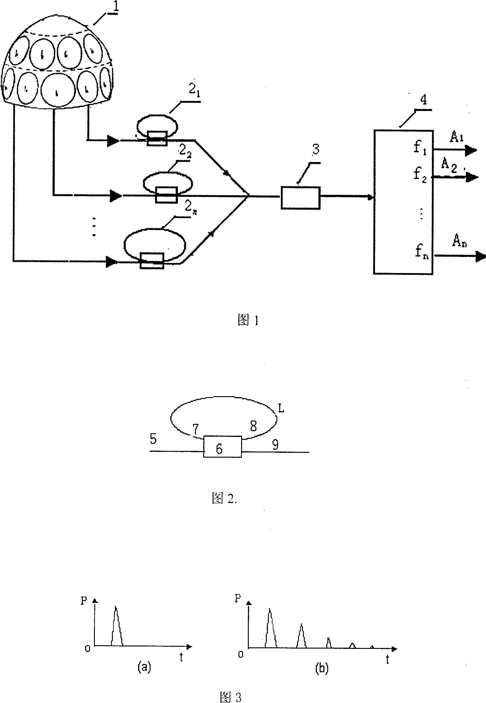
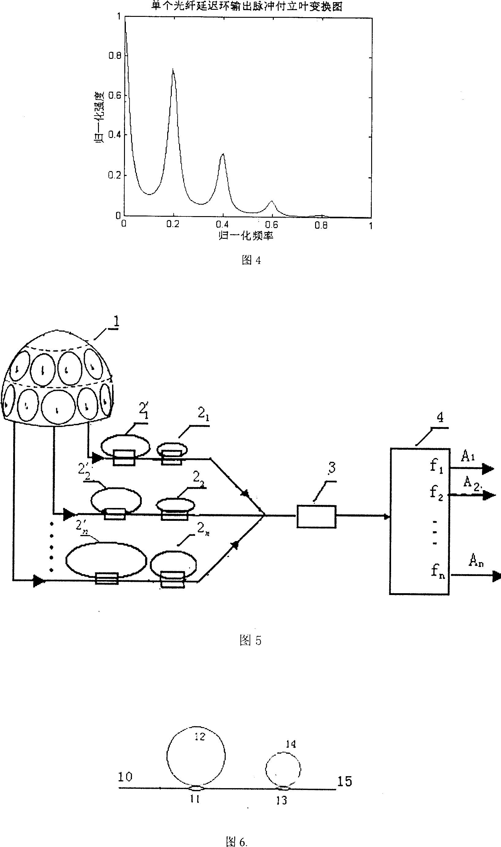
[0040] A dual-fiber ring cascaded laser warning device

[0041] The two cascaded fiber ring feedback units are shown in Figure 6, and a 2×2 fiber coupler can be used to connect the fiber, fiber ring, and fiber coupler.

[0042] Select the coupling coefficient of fiber coupler 10 as: k 1 =0.46, the coupling coefficient of fiber coupler 12 is: k 2 =0.38, the input light pulse intensity is normalized to 1.

[0043] The optical impulse responses A and B of the two fiber rings are obtained by formula (1):

[0044] A=[0.46 0.292 0.134 0.062 0.028 0.013 0.006...]

[0045] B=[0.38 0.384 0.146 0.0555 0.021 0.008 0.003...]

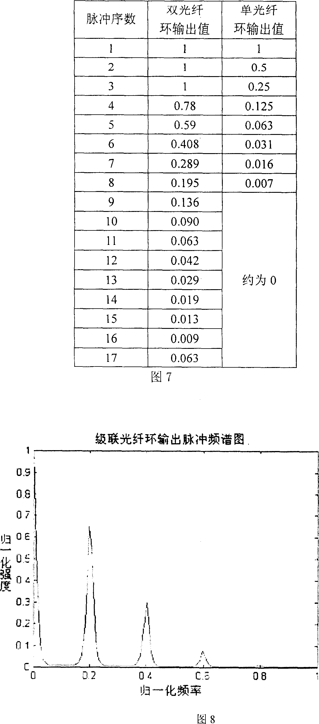
[0046] The impulse response of the cascaded optical fiber ring is obtained from formula (2) and A, B:

[0047] C=[0.1748 0.1768 0.1780 0.1376 0.1033 0.0714 0.05060.0340 0.0237 0.0158 0.0110 0.0073 0.0051 0.0034 0.00230.0015 0.0011 0.0007  …

[0048] When the input optical pulse power of the cascaded fiber ring is 1, the output pulse power val...


PUM


Abstract

The double fiber ring cascading laser alarm has feedback unit comprising two cascade fiber rings to replace the feedback unit comprising single fiber ring in available technology, and the two fiber rings have length in integral number times. By means of the temporary storage of the fiber ring and power re-distribution of the fiber coupler, the degressive pulse sequence the fore stage of the fiber ring outputs may have its power re-distributed to improve the frequency domain characteristic of the output pulse sequence. Therefore, the double fiber ring cascading laser alarm of the present invention has the features of obvious characteristic frequency of output pulse sequence, less cross-talk between optical windows and high system precision. The present invention may be used in laser orientation distinction, location and other military reconnaissance fields.

Description

Technical field: [0001] The invention belongs to the field of optoelectronic technology, and in particular relates to laser warning technology. Background technique [0002] As we all know, using laser warning technology to identify enemy threats and their threat locations can effectively protect our important equipment and other platforms. Therefore, the research on laser warning technology has received extensive attention. The existing frequency coded laser warning system uses the optical fiber loop feedback unit to output the pulse frequency to identify the optical antenna. Fig. 1 is a structural schematic diagram of this alarm system, which consists of an optical antenna direction recognition sensing head (hemispherical sensing head) 1, an optical fiber coupler 6, and n single fiber rings: 2 1 ,2 2 ,…,2 n (n is the number of optical antennas in the direction recognition sensor head 1, and each single fiber ring is formed by connecting the two ends of the optical fibe...

Claims


Application Information

Patent Timeline
Patent Type & Authority Patents(China)
IPC IPC(8): G01S17/74G01S7/481G01S3/784
CPCG01S7/4818G01S7/4804
Inventor 周晓军白晓明曾钦勇
Owner UNIV OF ELECTRONICS SCI & TECH OF CHINA
Why Eureka
Eureka Blog
Learn More