Battery holding unit

A battery and component technology, applied in the field of battery holding components, can solve problems such as mutual separation, and achieve the effect of firm combination and easy insertion operation.

Inactive Publication Date: 2002-03-13
ALPS ALPINE CO LTD
View PDF0 Cites 9 Cited by
  • Summary
  • Abstract
  • Description
  • Claims
  • Application Information

AI Technical Summary

Problems solved by technology

[0007] The present invention is an invention for solving the above-mentioned problems. The purpose of the present invention is to provide a flat type battery that can have good insertability when inserting a flat battery into the battery holding assembly, and can resist...

Method used


Image

  • Battery holding unit
  • Battery holding unit
  • Battery holding unit

Examples


Embodiment Construction

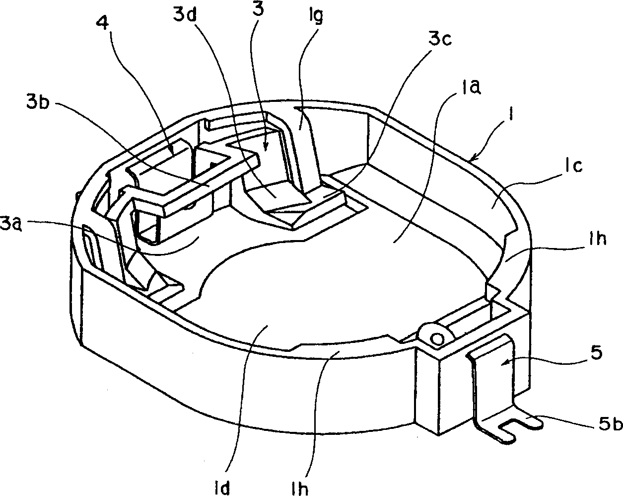
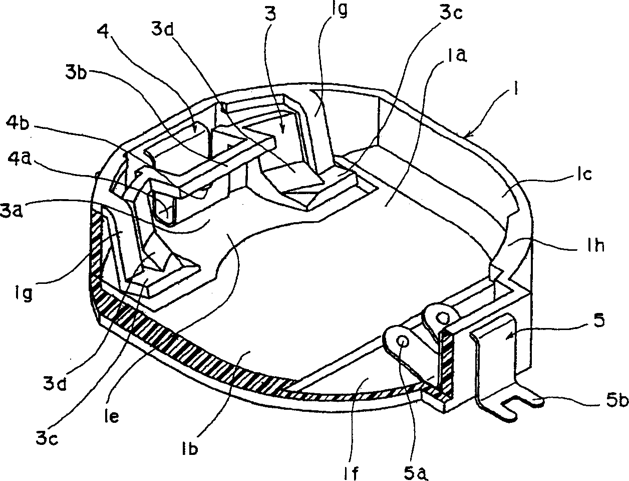
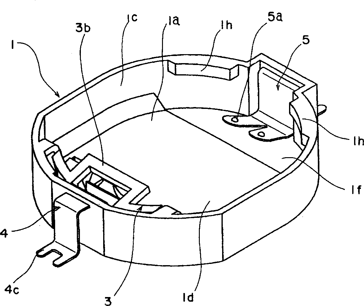
[0034] Refer below Figure 1 to Figure 11 , to illustrate the first embodiment of the present invention. figure 1 To show a schematic oblique view of a battery holding assembly constructed according to the present invention, figure 2 to express as figure 1 A schematic oblique view of the battery holding assembly shown when it is partially cut away, image 3 To represent by and such figure 1 A schematic oblique view of the battery holding assembly when viewed from different directions as shown, Figure 4 to express as image 3 A schematic oblique view of the battery holding assembly shown when it is partially cut away, Figure 5 It is a schematic oblique view showing the state when the battery is inserted into the battery holding assembly, Image 6 To represent by and such Figure 5 A schematic oblique view for observing the state of the battery inserted into the battery holding assembly from a different direction than the one shown, Figure 7 A schematic explanator...


PUM


Abstract

A battery holder structure for a flat battery is to be provided allowing the battery, when it is to be inserted into the battery holder, to be readily inserted and, at the same time, to be firmly engaged and to be prevented from springing out of the case or its contacts from becoming disconnected when any vibration or impact from outside is suffered. <??>In a case 1 having in its top face an opening 1d through which a battery 2 is to be inserted, protruding barriers 1h are formed toward one end of the opening 1d to engage with the top face of the inserted battery 2 to prevent the battery 2 from coming off, and a battery holding section 3 having elastically deformable elastic arms 1g is formed toward the other end of the opening 1d in the case 1 opposite these protruding barriers 1h, the arms 1g turning toward the bottom plate 1b along with the insertion of the battery 2 and pressing the peripheral face 2a of the battery 2 toward the peripheral wall 1c.

Description

technical field [0001] The present invention relates to a battery holding unit that can be used as a memory support unit of various electronic devices such as game software equipment and office equipment, and particularly relates to a battery holding unit that can accommodate a flat type battery. Background technique [0002] A battery holding assembly for a flat battery in the prior art such as Figure 14 to Figure 16 shown. Figure 14 To show a schematic plan view for such a battery holding assembly, Figure 15 to indicate along Figure 14 A schematic cross-sectional view when cut along line 15-15, Figure 16 to indicate along Figure 14 A schematic oblique view of the state when the line 15-15 is cut. [0003] As shown in these figures, the housing 31 may be made of an insulating material such as synthetic resin, formed generally in a cylindrical shape having an opening at its upper portion. A bottom plate portion 31a corresponding to one side surface on the flat typ...

Claims


Application Information

Patent Timeline
IPC IPC(8): H01M2/10
CPCY02E60/12H01M2/1044H01M50/216Y02E60/10
Inventor 二官伸之
Owner ALPS ALPINE CO LTD
Why Eureka
Try Eureka