Adaptive hot gas bypass control for centrifugal chillers

A technology of hot gas bypass valve and centrifugal compressor, which is applied in the direction of pump control, refrigerator, refrigeration components, etc., and can solve problems such as fluctuating states

Inactive Publication Date: 2002-03-13
YORK INT
View PDF2 Cites 10 Cited by
  • Summary
  • Abstract
  • Description
  • Claims
  • Application Information

AI Technical Summary

Problems solved by technology

Too much valve opening can result in numerous operations...

Method used


Image

  • Adaptive hot gas bypass control for centrifugal chillers
  • Adaptive hot gas bypass control for centrifugal chillers
  • Adaptive hot gas bypass control for centrifugal chillers

Examples


Embodiment Construction

[0016] The following description of embodiments of the invention refers to the accompanying drawings. Accordingly, the same reference numerals in different figures refer to the same or similar elements.

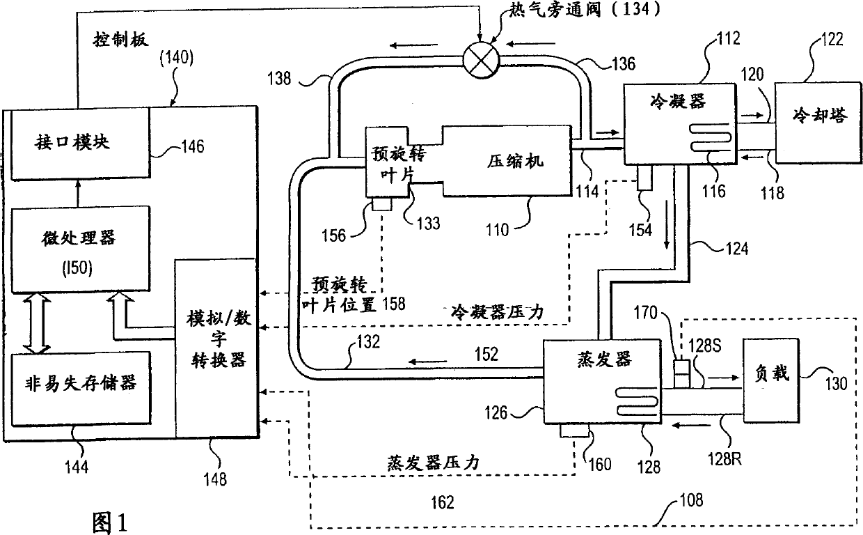
[0017] Figure 1 is a diagram of a refrigeration system 100 and control panel in accordance with the present invention. Refrigeration system 100 includes a centrifugal compressor 110 that compresses refrigerant vapor and provides it to condenser 112 via line 114 . Condenser 112 includes a heat exchanger tube bundle 116 having an inlet 118 and an outlet 120 connected to a cooling tower 122 . Condensed liquid refrigerant from condenser 112 flows to evaporator 126 via line 124 . The evaporator 126 includes a heat exchanger tube bundle 128 having a supply line 128S and a return line 128R connected to a cooling load 130 . Vapor refrigerant in the evaporator 126 returns to the compressor 110 via a suction line 132 containing a pre-rotational vane (PRV) 133 . A hot gas bypass (HG...


PUM


Abstract

An adaptive control apparatus and a method for automatically controlling a refrigeration system (100) as a function of cooling load and head. A control panel (140) controls the operation of a hot gas bypass valve (134) so as to avoid surging of the compressor (110) in response to cooling load and head. The control apparatus and method also allow for automatic self calibration.

Description

technical field [0001] This invention relates generally to refrigeration or cooling systems, and more particularly to apparatus and methods for controlling a hot gas bypass valve to eliminate or reduce surges in centrifugal liquid cooler systems. Background technique [0002] It is well known that surge or surge is an unstable condition that may occur when a compressor, such as a centrifugal compressor, operates at a light load and high pressure ratio. It is a transient phenomenon characterized by frequent vibrations in pressure and flow, and in some cases in diametrically opposite directions, through the compressor. If not controlled, such surges produce excessive oscillations and can lead to permanent damage to the compressor. Furthermore, if the driving device is a motor, surge causes excessive power consumption. [0003] Hot gas bypass is known to help avoid compressor surge at low or part load conditions. As cooling loads decrease, hot gas bypass is required to incre...

Claims


Application Information

Patent Timeline
IPC IPC(8): F04D27/02F25B1/053F25B41/04F25B49/02
CPCF04D27/0207F25B49/02F25B1/053F25B2600/0261F25B41/043F25B41/04F25B2700/195F25B2700/197
Inventor 格埋戈里·K·比佛森哈罗德·B·金德尔丹尼斯·L·德伊兹
Owner YORK INT
Why Eureka
Try Eureka