Supercharge Your Innovation With Domain-Expert AI Agents!

Dynamic load balance device

A technology of load balancer and balancer, which is applied in the field of communication network and can solve problems such as inappropriate

Inactive Publication Date: 2002-06-19
AVAYA COMM ISRAEL
View PDF0 Cites 9 Cited by
  • Summary
  • Abstract
  • Description
  • Claims
  • Application Information

AI Technical Summary

Problems solved by technology

However, these accelerators are not suitable for use with half-NAT and full-NAT load balancers, because changing the IP address by the load balancer prevents the accelerator from finding an entry in this table that matches packets forwarded to the server

Method used


Image

  • Dynamic load balance device
  • Dynamic load balance device
  • Dynamic load balance device

Examples


Embodiment Construction

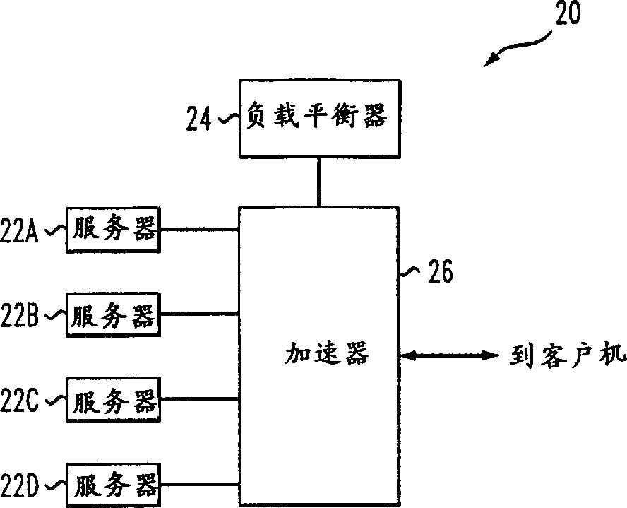
[0043] figure 1 is a schematic block diagram of a server farm 20 according to an embodiment of the present invention. Server farm 20 includes a plurality of servers 22 (numbered 22A, 22B, 22C, and 22D) that host an Internet site. Data packets transmitted to the website, ie, with the IP address of the website, are routed to the load balancer 24, which determines which server 22 should forward the data packet. Preferably, the server farm 20 works according to a semi-NAT scheme, ie the load balancer replaces at least one IP destination address and / or TCP / UDP destination port field of data packets it forwards to the servers 22 . Additionally, the load balancer 24 operates in a delta mode. Additionally, as described below, load balancer 24 operates according to a full NAT scheme.

[0044] Accelerator 26 acts as a switch for routing packets between load balancer 24 and clients and between load balancer 24 and servers 22 . The accelerator 26 determines from at least some of the d...


PUM


Abstract

The present invention relates to a method of accelerating the operation of a load balancer by an accelerator switch. The method includes receiving, by the accelerator switch, packets directed to the load balancer, determining, for at least some of the received packets, whether the packets match an entry of a list of packet groups, by comparing fewer than five parameters of the packets to respective fields of entries of the list, and forwarding, by the accelerator switch, at least one of the received packets, directly to their destination, responsive to the determining.

Description

technical field [0001] The present invention relates to communication networks and in particular to server load balancing in such networks. Background technique [0002] A busy site usually consists of a cluster of multiple servers, each handling connections to a subset of clients. Typically, such a group of servers includes a load balancer for receiving data packets (also known as frames) transmitted to the network addresses of the group. The load balancer distributes the packets among the multiple servers containing the web address such that all packets for a single client session are delivered to a single server. Server load balancers are also used for other purposes, such as redirecting packets to proxy caches. [0003] In some cases, the load on the load balancer is very high and an additional and / or newer load balancer is required. However, replacing and / or adding a load balancer may require extensive programming effort such that the new balancer operates according ...

Claims


Application Information

Patent Timeline
Patent Type & Authority Applications(China)
IPC IPC(8): G06F15/177G06F13/00H04L12/44H04L12/46H04L12/56
CPCH04L47/10H04L47/125H04L47/122
Inventor 莱尔·沙别塔伊
Owner AVAYA COMM ISRAEL
Features
  • R&D
  • Intellectual Property
  • Life Sciences
  • Materials
  • Tech Scout
  • Unparalleled Data Quality
  • Higher Quality Content
  • 60% Fewer Hallucinations
Learn More