Eureka AIR delivers breakthrough ideas for toughest innovation challenges, trusted by R&D personnel around the world.

Picture coding method, picture coding equipment and image repeating equipment

A coding device and coding method technology, applied in the field of picture coding devices, can solve problems such as inability to set the total amount of codes, inability to effectively use the total amount of codes, and deterioration of image quality.

Inactive Publication Date: 2002-06-19
PANASONIC CORP
View PDF0 Cites 8 Cited by
  • Summary
  • Abstract
  • Description
  • Claims
  • Application Information

AI Technical Summary

Problems solved by technology

results, such as Figure 12 As explained in the transcoding device shown, when no picture can be input at the coded frame rate suitable for the setting, an efficient total code allocation cannot be achieved
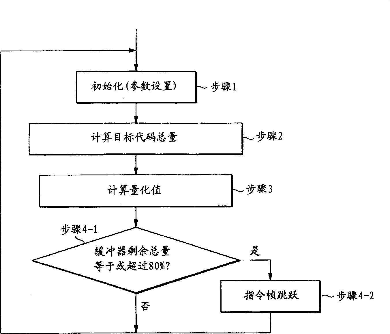
[0045] Second, when the encoding frame rate is set to a large encoding frame rate to solve the above problem, there is another problem that the frame skipping operation occurs multiple times
In this case, the (moving) picture to be output may become a (moving) picture lacking in smoothness compared to the input (moving) picture
Moreover, the total amount of code associated with the originally coded picture becomes useless and the image quality will deteriorate
[0047] As previously described, when a conventional rate control system is implemented in a system switching device, the following problems may occur: namely, (1) since the frame rate of an input picture is unknown and varies, an appropriate amount of code cannot be set, and Inefficient use of this amount of code that can be used raw makes image quality worse

Method used


Image

  • Picture coding method, picture coding equipment and image repeating equipment
  • Picture coding method, picture coding equipment and image repeating equipment
  • Picture coding method, picture coding equipment and image repeating equipment

Examples


Embodiment Construction

[0070] Hereinafter, embodiments of the present invention will be described with reference to the drawings.

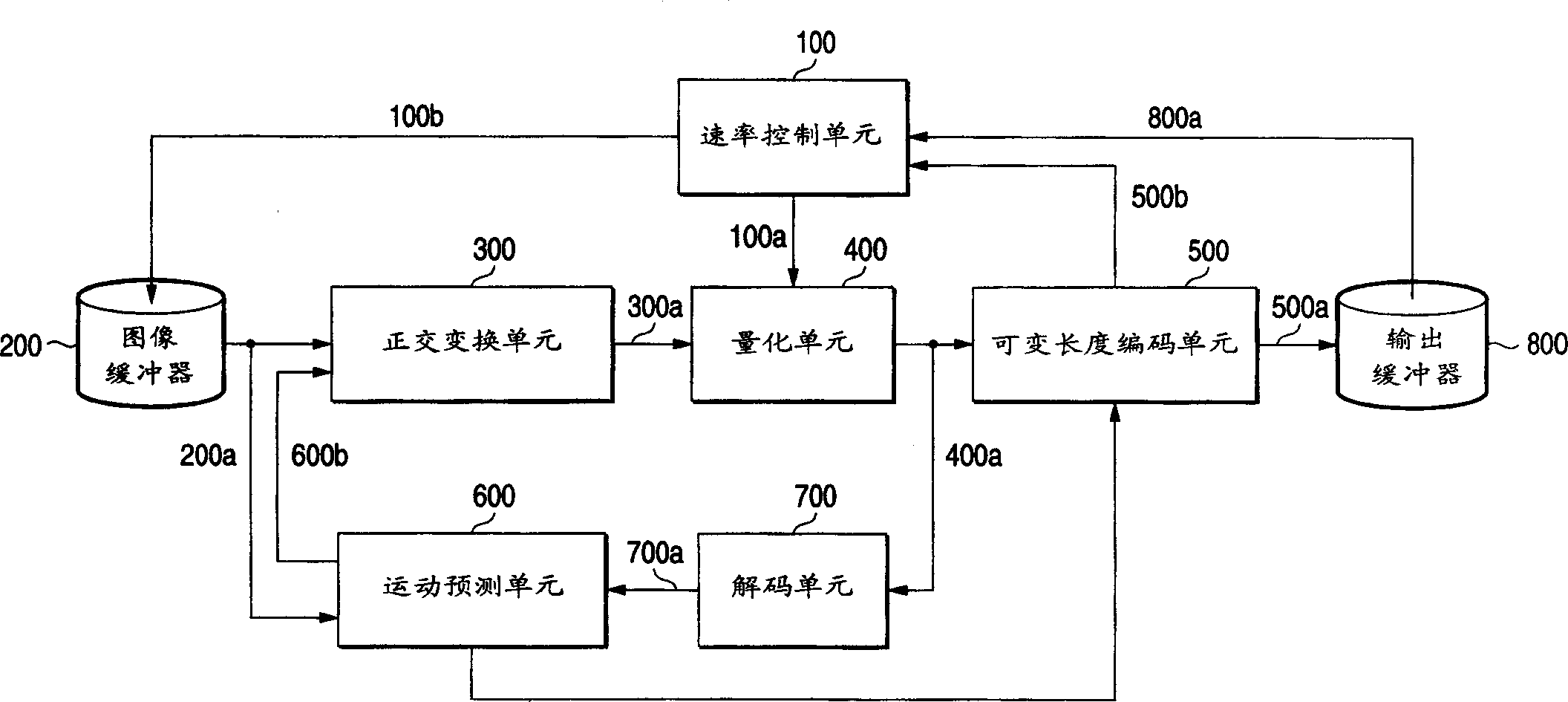
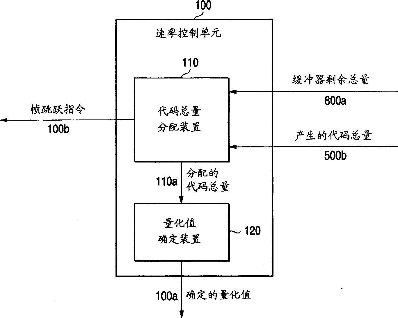
[0071] figure 1 is a functional block diagram showing the configuration of the picture encoding device according to the first embodiment of the present invention. This picture encoding device is realized based on an encoding operation of a general-purpose compression system that is Recommendation H.261 of ITU-T and MPEG-4. An uncompressed picture is input into the picture encoding device, and an encoded signal is output therefrom. As an input uncompressed picture, such a picture may use an unknown frame rate and a frame rate that changes dynamically due to frame skip operations and the like. The picture coding apparatus includes a rate control unit 100 , an image buffer 200 , an orthogonal transformation unit 300 , a quantization unit 400 , a variable length coding unit 500 , a motion prediction unit 600 , a decoding unit 700 , and an output buffer 800 .

[0072] Th...


PUM


Abstract

The invention relates to a picture coding device, a picture coding method and image repeater facility used for recoding digit compressed picture signals to obtain digit picture signals with the compressed format which is the same to or different from the compressed format of the digit compressed picture signals to be recoded. A picture coding apparatus contains a rate control unit, an image buffer, an orthogonal transformation unit, a quantizing unit, a variable length coding unit, a motion predicting unit, a coding unit, and an output buffer. The rate control unit allocates a target code amount to each of pictures, and transfers a quantizing value which is determined by a code amount to the quantizing unit. This target code amount is calculated by adding a reference target code amount to a correction value. The correction value is calculated based on a difference between a predetermined target value and an actual value of a remaining coding picture amount of the output buffer.

Description

technical field [0001] The present invention relates to a picture encoding device and a picture encoding method for re-encoding a digitally compressed picture signal to obtain a digital picture signal having the same or different compression format as that of the digitally compressed picture signal. More particularly, the present invention relates to the ability to increase the bit usage when a digitally compressed picture signal is re-encoded as an input picture signal to reduce the number of frame skip operations in the case where the total number of frames of the digitally compressed picture signal per unit time is varied. Efficient picture encoding device and picture encoding method. Background technique [0002] A video conferencing system using a narrowband ISDN is generally used practically. Such a video conferencing system can be implemented by a picture compression technology capable of compressing digitized meeting pictures to obtain a pre...

Claims


Application Information

Patent Timeline
Patent Type & Authority Applications(China)
IPC IPC(8): G06T9/00
CPCG06T9/005
Inventor 上野山努山田和范
Owner PANASONIC CORP
Why Eureka
Eureka Blog
Learn More