Optical fibre sensor installed easily and music instrument using it
A technology of optical sensor and sensor head, applied in the field of optical sensor, can solve the problems of consuming time and manpower, increasing production cost, etc.
- Summary
- Abstract
- Description
- Claims
- Application Information
AI Technical Summary
Problems solved by technology
Method used
Image

Examples
Example
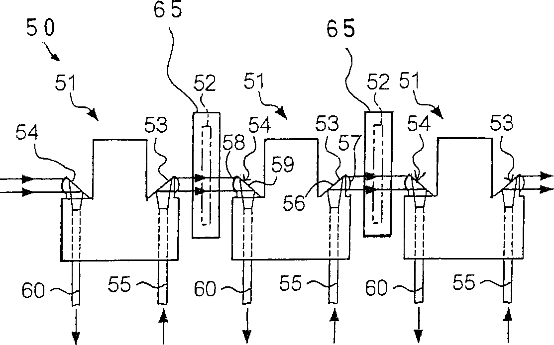
[0060] It should be understood that the hammer 4 requires only one combined optical element. Therefore, the combined optical element 3c is reduced to half of the combined optical element in the prior art optical fiber sensor array. Second embodiment
[0061] See attached Figure 8 with 9 , The other sensor head 20 forms a part of the optical fiber sensor, and the optical fiber sensor is used in another automatic performance piano according to the embodiment of the present invention. The sensor head 20 is a monolithic integrated circuit main body, and is not divided into a plurality of parts, such as the head main body 10 and the jig 11 and so on. Except for the optical fiber sensor, the automatic performance piano implemented in the second embodiment is similar to the first embodiment. In order to avoid undesired repetition, the description is mainly focused on the optical fiber sensor.
[0062] The optical fiber sensor array also includes a sensor head 20, an optical fiber bundle...
Example
[0070] It should be understood that the wings 21a / 21b elastically press the optical fiber 9 toward the head body portion 20a, and the installation between the sensor head 20 and the optical fiber 9 does not require any adhesive. The installation work will not consume a long time, which reduces the production cost. The third embodiment
[0071] Picture 10 It shows a sensor head 30 used in an automatic performance piano according to another embodiment of the present invention. The automatic performance piano implemented in the third embodiment is similar to the first embodiment except for the optical fiber sensor. In order to avoid undesired repetition, the description is mainly focused on the optical fiber sensor.
[0072] The optical fiber sensor array also includes a sensor head array 30, an optical fiber bundle 3b, a combined optical element 3c, a filter plate 5, and a clamper 31. The combined optical element 3c and the optical fiber bundle 3b are similar to that of the optica...
Example
[0079] It should be understood that the optical fiber 9 is sandwiched between the sensor head 30 and the tongue 32, and no adhesive is required during installation. Workers can complete the installation work without a long time, reducing production costs. Fourth embodiment
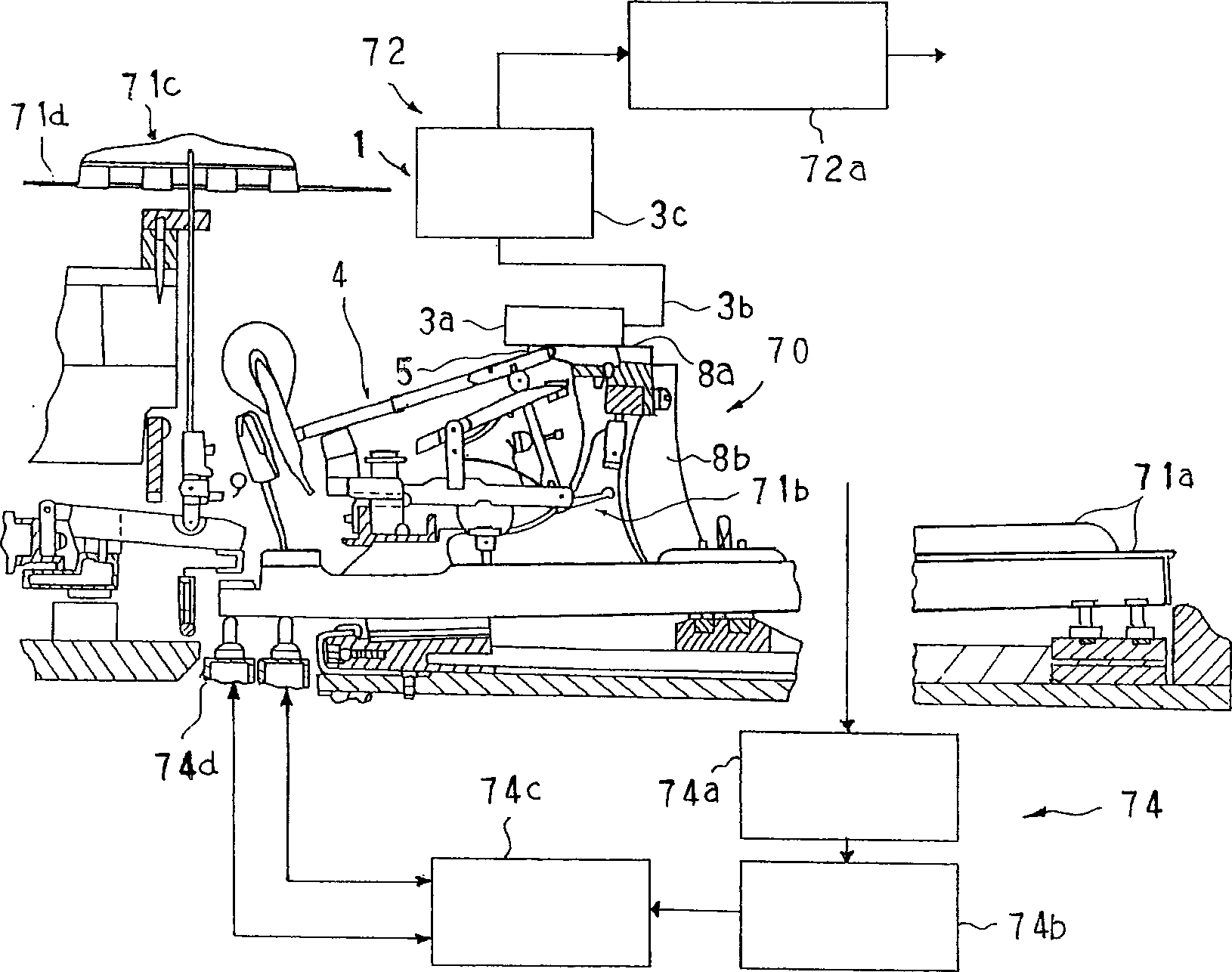
[0080] See attached Picture 12 The silent piano of the embodiment of the present invention mainly includes an acoustic piano 81, a hammer stopper 82, and an electronic tone generation system 83. The acoustic piano is similar to the acoustic piano 70, and the hammer stopper 82 can be changed between a free position and a blocking position. The hammer stopper 82 at the free position exceeds the trajectory of the hammer rod 4a, and the hammer device 4 strikes the relevant string 71d without any interference with the hammer stopper 82. On the other hand, when the hammer stopper 82 rotates 90 degrees clockwise, the hammer stopper 82 enters the trajectory of the hammer lever 4a and changes to the blocking position....
PUM
 Abstract
Description
Claims
Application Information
 - R&D Engineer
- R&D Manager
- IP Professional
- Industry Leading Data Capabilities
- Powerful AI technology
- Patent DNA Extraction
Browse by: Latest US Patents, China's latest patents, Technical Efficacy Thesaurus, Application Domain, Technology Topic.
© 2024 PatSnap. All rights reserved.Legal|Privacy policy|Modern Slavery Act Transparency Statement|Sitemap