Engine for motor bicycle

A technology for motorized two-wheeled vehicles and engines, which is applied in the direction of machines/engines, motor vehicles, engine components, etc., and can solve problems such as obstruction, shortening the distance between the crankshaft and the transmission output shaft, shortening the overall length of the engine, etc., to reduce side thrust , Fuel cost improvement, and the effect of reducing sliding frictional resistance

Inactive Publication Date: 2002-09-18
HONDA MOTOR CO LTD
View PDF1 Cites 1 Cited by
  • Summary
  • Abstract
  • Description
  • Claims
  • Application Information

AI Technical Summary

Problems solved by technology

[0003] In this motorcycle engine, the shift input shaft is disposed upwardly relative to the plane containing the two axes of the crankshaft and the shift output shaft, which can effectively shorten the distance between the crankshaft and the shift output shaft, thereby shortening the front and rear of the engine. The overall length in the direction can be reduced, but in the existing engine, the upper offset of the transmission input shaft cannot be obtained sufficiently due to the hindrance of the cylinder block.

Method used


Image

  • Engine for motor bicycle
  • Engine for motor bicycle
  • Engine for motor bicycle

Examples


Embodiment Construction

[0016] The implementation form of the present invention will be described below according to an embodiment of the present invention shown in the drawings.

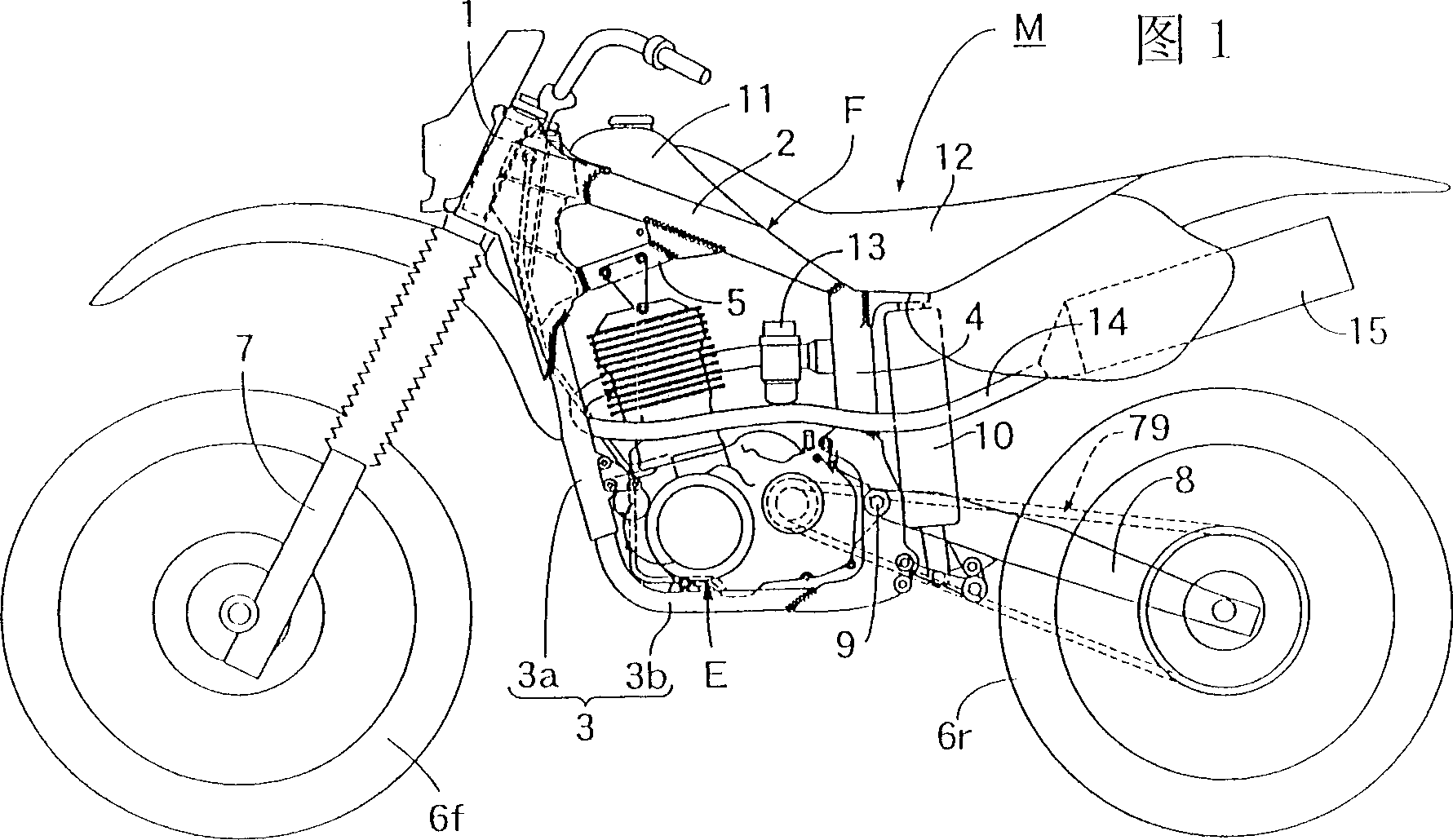
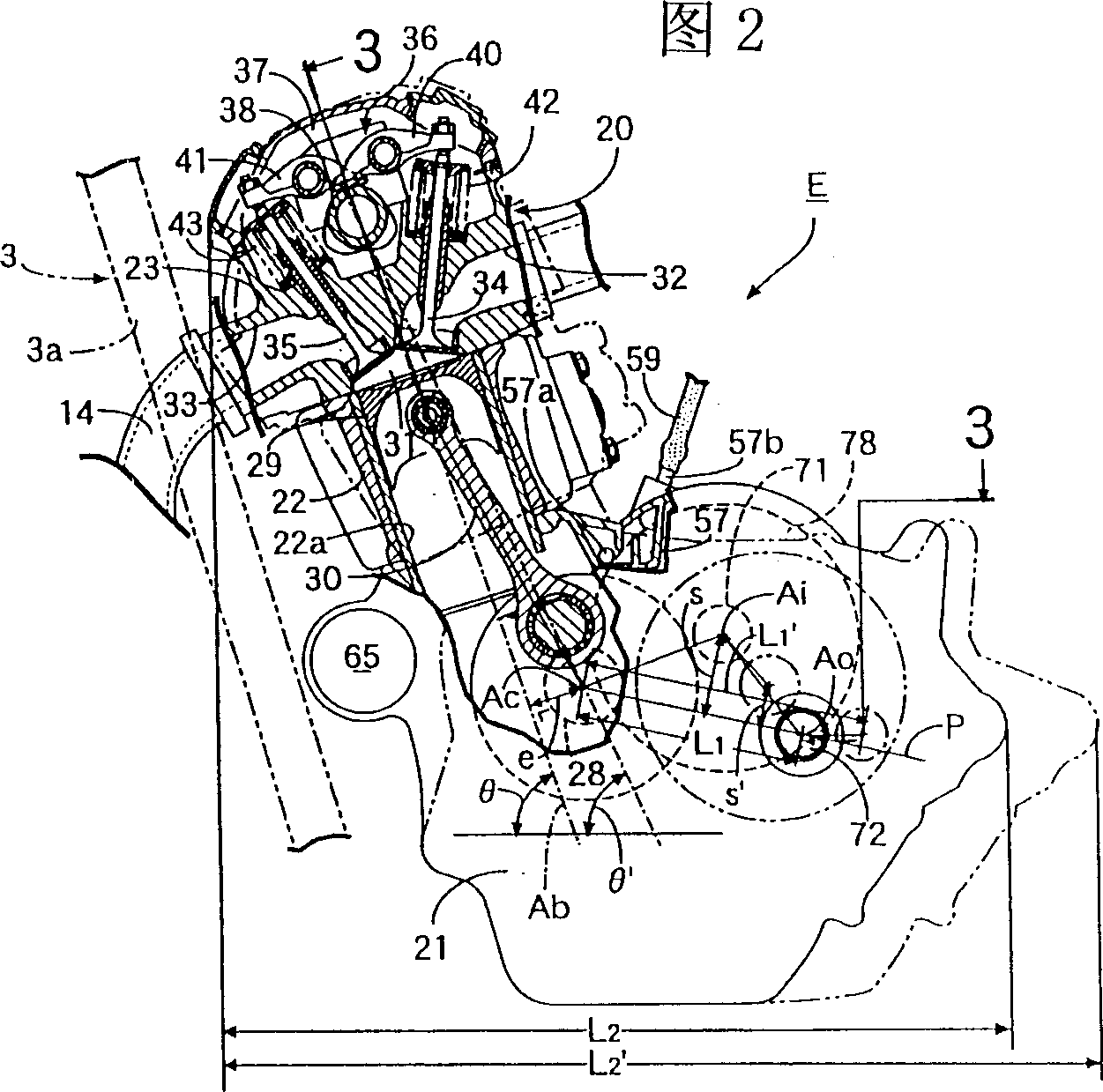
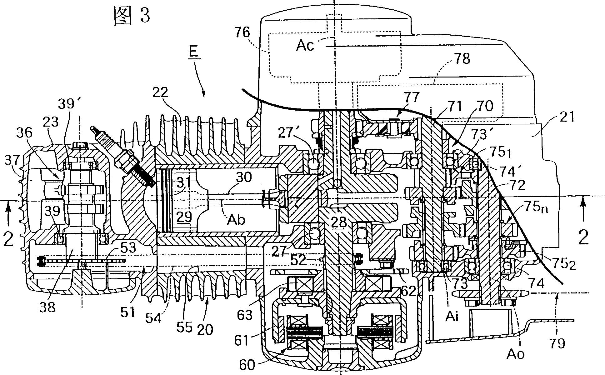
[0017] Fig. 1 is a side view of a motorcycle equipped with an engine of a first embodiment of the present invention, Fig. 2 is a vertical side view of the above-mentioned engine, Fig. 3 is a sectional view taken along line 3-3 of Fig. 2 , and Fig. 4 is a sectional view of the engine It is a longitudinal sectional side view of the engine of the second embodiment of the invention.

[0018] In the following description, front, rear, left, and right are based on the motorcycle M to which the present invention is applied.

[0019] First, a first embodiment of the present invention shown in FIGS. 1 and 2 will be described. In FIG. 1 , a frame F of a motorcycle M has a head pipe 1 , a main pipe 2 welded to the upper portion of the head pipe 1 and extending rearward and downward with a gentle slope, and a lower pipe 2 welded to t...


PUM


Abstract

An engine for a motorcycle, comprising a cylinder block 22 extending from the upper front end of a crankcase 21 toward the upper front of a motorcycle M, facing a plane P including two axes Ac and Ao of a crankshaft 28 and an output shaft 72. The input shaft 71 is arranged offset above; the cylinder block 22 is arranged so that its axis Ab passes through the axis Ac of the crankshaft 28 in front. In this way, the upper deviation of the transmission input shaft is sufficiently increased without being hindered by the cylinder block, and the overall length of the engine in the front-rear direction is shortened.

Description

technical field [0001] The present invention relates to an engine for a motorcycle, and more particularly to an improvement of an engine for a motorcycle. The engine for a motorcycle has a crankcase and a cylinder extending from the upper front end of the crankcase toward the upper front of the vehicle. body, and the cylinder head joined to the upper end of the cylinder block, the crankshaft, the transmission input shaft, and the transmission output shaft, which are accommodated and supported by the crankcase, are arranged so that the axis of the crankshaft faces the left and right directions of the vehicle. The plane of the two axes of the shaft deviates upwards and arranges the transmission input shaft. Background technique [0002] In a conventional motorcycle engine, the cylinder block is generally arranged such that its axis intersects the axis of the crankshaft (for example, refer to Japanese Patent Application Laid-Open No. 11-29085). [0003] In this motorcycle engi...

Claims


Application Information

Patent Timeline
Patent Type & Authority Applications(China)
IPC IPC(8): B62M7/02F01B9/02F02B61/02F02B75/16F02B75/18F02B75/22F02B75/26F02F1/24F02F7/00
CPCF02B61/02F02B75/16F02B75/22F02B2075/1808F02B2275/20F02F7/0019F02F2001/245F02B75/26
Inventor 铃木正刚久保田良
Owner HONDA MOTOR CO LTD
Why Eureka
Try Eureka