Apparatus for controlled curved sawing or cutting of two-faced cants

a technology of curved sawing and control system, which is applied in the direction of feeding apparatus, automatic control devices, precision positioning equipment, etc., can solve the problems of inability to effectively limit the cutting curve, entail important losses in lumber yield, and deformities that alter the perception of the basic shape of the piece by surface deformations, etc., to reduce side thrust and reduce lateral stresses to the cutting elements

Inactive Publication Date: 2002-12-17
EQUIP COMACT INC COMACT EQUIP +1
View PDF16 Cites 12 Cited by
  • Summary
  • Abstract
  • Description
  • Claims
  • Application Information

AI Technical Summary

Benefits of technology

The purpose of this arrangement is to cause the workpiece (i.e. the two-faced cant) to follow, during its forward travel, a trajectory which will cause a suitable curving cut to be performed by the sawing or cutting unit. This result is accomplished by displacement, transversal to the feed axis, of preferably two moveable guiding units consisting of powered rollers clamping unto the horizontally parallel planar faces of the cant, in areas before and beyond the sawing or cutting unit, and continuously moving the cant laterally in opposite directions within those areas during its forward travel through the cut. These combined lateral motions are controlled in speed and direction by a computer interpretation of scanner data and they are further positionally interlocked by means of a control linkage connecting the two guiding units. The linkage effect, beyond insuring total motion synchronism, also establishes a fixed pivotal point for the workpiece, the location of which is determined by the geometry of the linkage itself. This latter feature of the system permits locating this pivotal point by design in the most favorable area to minimize lateral stresses to the cutting elements.
This preferred area lies between the cutting zone and the rotating axis of the saws or cutter heads so as to limit, on the one hand, lateral stresses on the cutting elements and, at the same time, keep any back rubbing of saw teeth or cutting knives at a practical minimum. It therefore becomes a matter of choice, within the scope of this invention, to locate the pivotal point for the workpiece somewhere between the cutting zone of the saw and its rotating axis, in order to reduce side thrust in said cutting zone and to strive at the same time towards equalizing side pressure on saw teeth in front and back. Both aims are worthwhile and can be reached with the present system, by adjustment of the workpiece pivotal point, through suitable proportioning of the linkage joining the two guiding units, as will be further explained in a detailed description of the diagram showing the general mechanical arrangements.

Problems solved by technology

In time, lumber producers have realized that straight line sawing along the length of a naturally curved two-faced cant could entail important losses in lumber yield.
However, during the past 20 years, sawing technology and market pressures have pushed feed rates beyond eight feet per second and new guiding methods for curved sawing had to be found.
Even if such devices respond to the general curvature of the workpiece, surface deformities alter their perception of the basic shape of the piece.
Besides, effective curve limiting in the cut is not possible because the guiding effect depends totally on contact with the natural surfaces of the piece, thus producing at times lumber that is bowed to such an extend as to cause problems in subsequent handling operations.

Method used


Image

  • Apparatus for controlled curved sawing or cutting of two-faced cants
  • Apparatus for controlled curved sawing or cutting of two-faced cants
  • Apparatus for controlled curved sawing or cutting of two-faced cants

Examples


Embodiment Construction

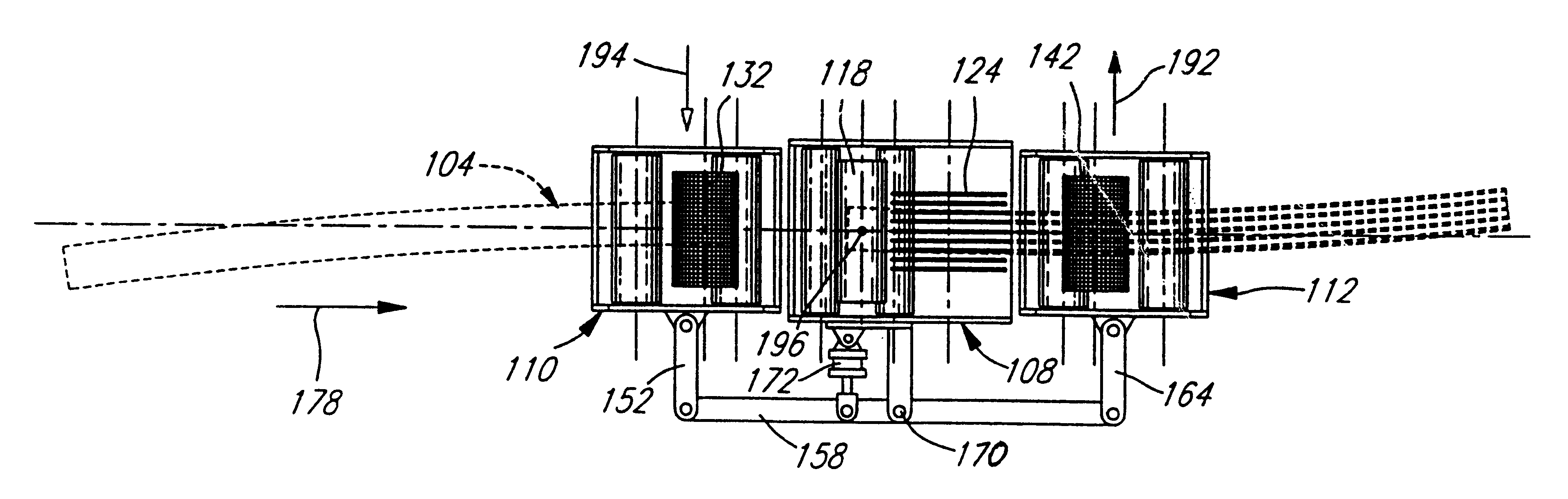
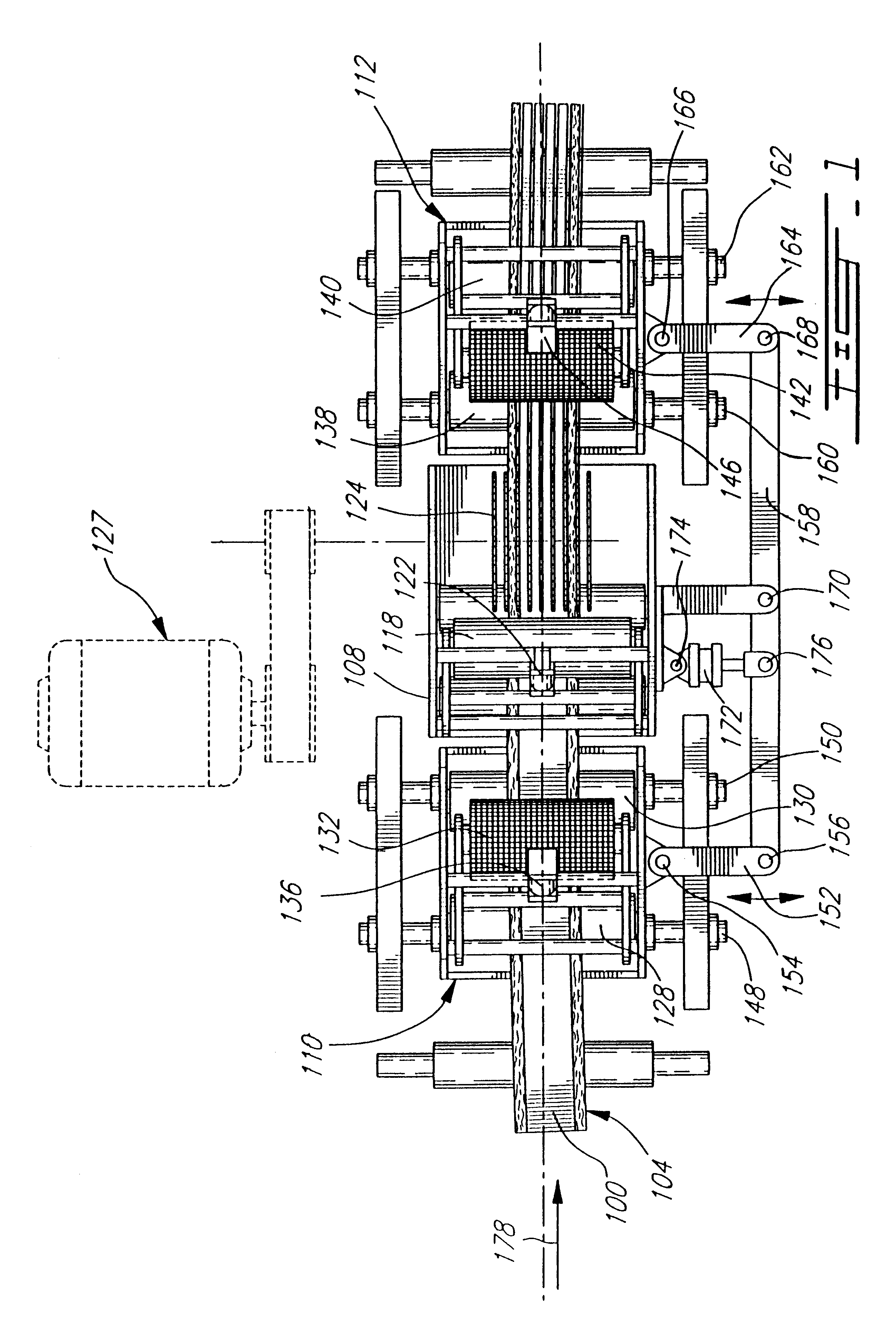
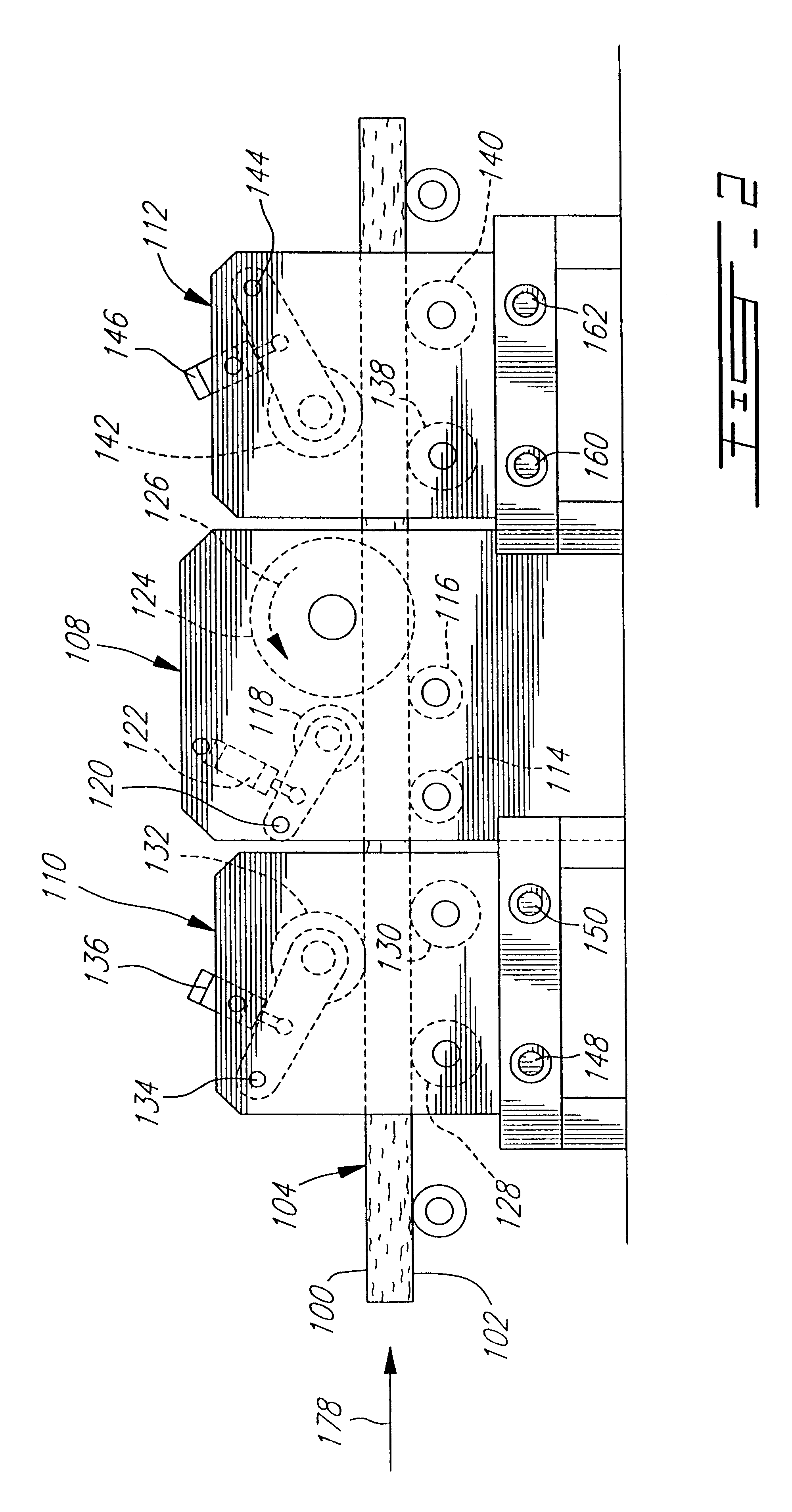
The following is a description of the curved cutting control system of the present invention, comprising mechanical components, such as motorized rollers having contact solely with the planar faces 100, 102 of a two-faced cant 104 in order to guide it through either final resawing (FIGS. 1-4) or a squaring off process (FIG. 6), whether in a straight line or along the natural curvature of the piece, as determined by previous dimension and form readings by a scanner 106 (see FIG. 5).

Referring more particularly to FIGS. 1 and 2, a cant resawing embodiment of the present invention is illustrated. Schematically, the embodiment comprises a processing unit 108 disposed between a pair of cant guiding units 110 and 112, respectively located upstream and downstream of unit 108. The latter comprises a pair of stationary lower rollers 114 and 116 and an upper roller 118 which may swing up or down about axis 120 by the action of a cylinder 122. The unit 108 also comprises a series of vertically ...


PUM

PropertyMeasurementUnit
angleaaaaaaaaaa
lengthaaaaaaaaaa
clamping pressureaaaaaaaaaa

Abstract

In combination with a cant sawing or cutting unit, a system for guiding two-faced cants through the cut along the line of their natural curvature which includes at the infeed and outfeed ends of the unit, laterally moveable rollers for clamping upon parallel planar faces of the cant and imparting to it a pivotal movement in the horizontal plane while it is moving forward through the cut, so that the saws or cutters follow along a controlled curve in relation to the natural curvature of the cant.

Description

The present invention relates to an apparatus for causing a controlled curved sawing or cutting of two-faced cants.A two-faced cant is produced by removing from a log, either by sawing or chipping, an approximately equal volume from each side, after such log has been rotated in an angular position which places its natural curvature in a plane parallel to the two faces to be obtained in the process. Such cants are subsequently resawn perpendicularly to the cut faces to produce lumber of such dimensions as required in the marketplace.While dimensional accuracy and edge straightness are requisites for this product, it has long been known that some bowing in a board across its thickness dimension, such as may occur in natural fiber stress relieving during the cut, is not detrimental to the quality of merchantable lumber since subsequent stacking and drying processes will straighten out any such curvature to a commercially acceptable degree.In time, lumber producers have realized that st...

Claims


Application Information

Patent Timeline
Patent Type & Authority Patents(United States)
IPC IPC(8): B27B1/00B27B25/02B27B31/06B27B25/00B27B31/00
CPCB27B1/007B27B25/02B27B31/06Y10T83/155Y10T83/178Y10T83/531Y10T83/536
Inventor BRISSON, MAURICE
Owner EQUIP COMACT INC COMACT EQUIP
Why Eureka
Try Eureka