Ratchet wrench with jamming-preventing and indicating functions

A ratchet wrench and anti-jamming technology, which is applied in the field of ratchet wrenches, can solve the problems of inability to know the wrench turning direction, wrong turning direction, and increasing processing procedures.

Inactive Publication Date: 2002-09-25
林彦文
View PDF0 Cites 7 Cited by
  • Summary
  • Abstract
  • Description
  • Claims
  • Application Information

AI Technical Summary

Problems solved by technology

[0003] For the traditional ratchet wrench with one-way locking, the user generally cannot know the direction of the wrench's turning, and it is easy to turn the wrench in the wrong direction during operation and use, so the wrench needs to be turned over and then placed on the screw. Turning the wrench wastes a lot of precious time. If a mark needs to be marked on the outer edge of the wrench for identification, it needs to be processed separately, which will increase the processing procedure and increase the production cost.
Please refer to the view of the existing related wrench, which is a Chinese Taiwan patent (patent announcement number 431260, titled "improved wrench structure"), and its main technical content is assembled with a clamping block in the ratchet wrench accommodation space 24 30 and a sliding top block 40, the sliding top block 40 is provided with a protruding swing fulcrum 41 on one side corresponding to the accommodating space 24, and two protrusions 42 are provided on the side corresponding to the stepped through hole, the sliding top block 40 The concave-convex tooth shape of the ratchet 52 of the sleeve ring 50 and the protrusions 42 on both sides can be used to push against each other, so that the sliding top block 40 can continuously swing without displacement, and the elastic component 44 at one end of the sliding top block 40 can be used to maintain The one-way clamping force of the ratchet 32 ​​of the clamping block 30, t

Method used


Image

  • Ratchet wrench with jamming-preventing and indicating functions
  • Ratchet wrench with jamming-preventing and indicating functions
  • Ratchet wrench with jamming-preventing and indicating functions

Examples


Embodiment Construction

[0050] Please refer to Figure 1 to Figure 9 , the wrench shown in the figure is the structure of the selected embodiment of the present invention, which is for illustration only, and the protection scope of the application is not limited by this structure.

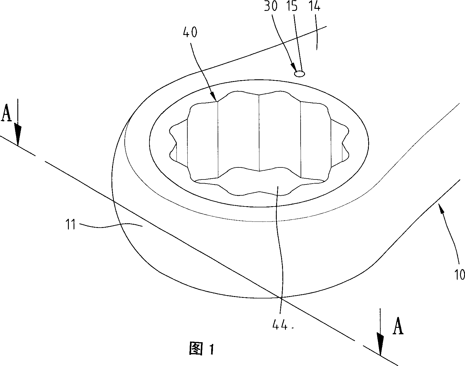
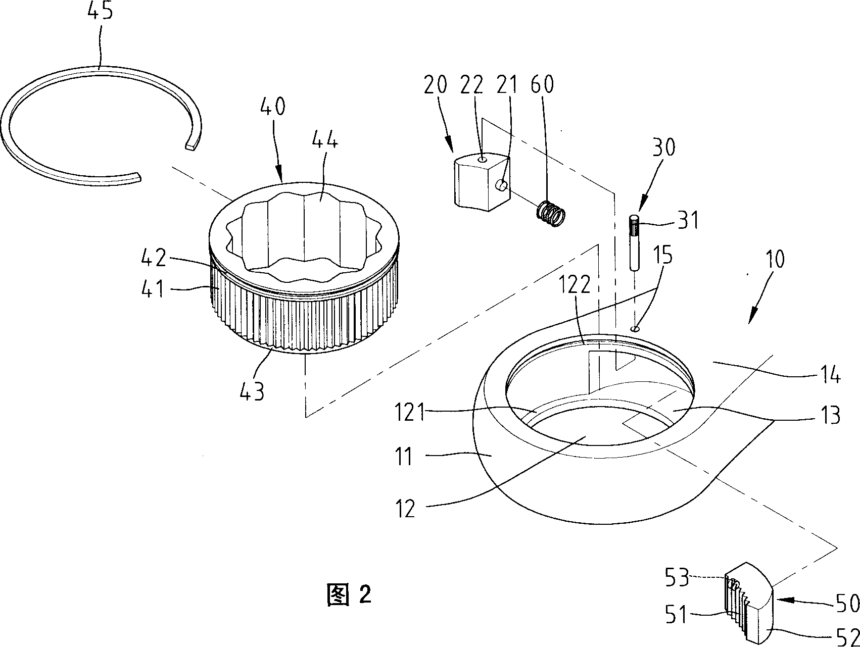
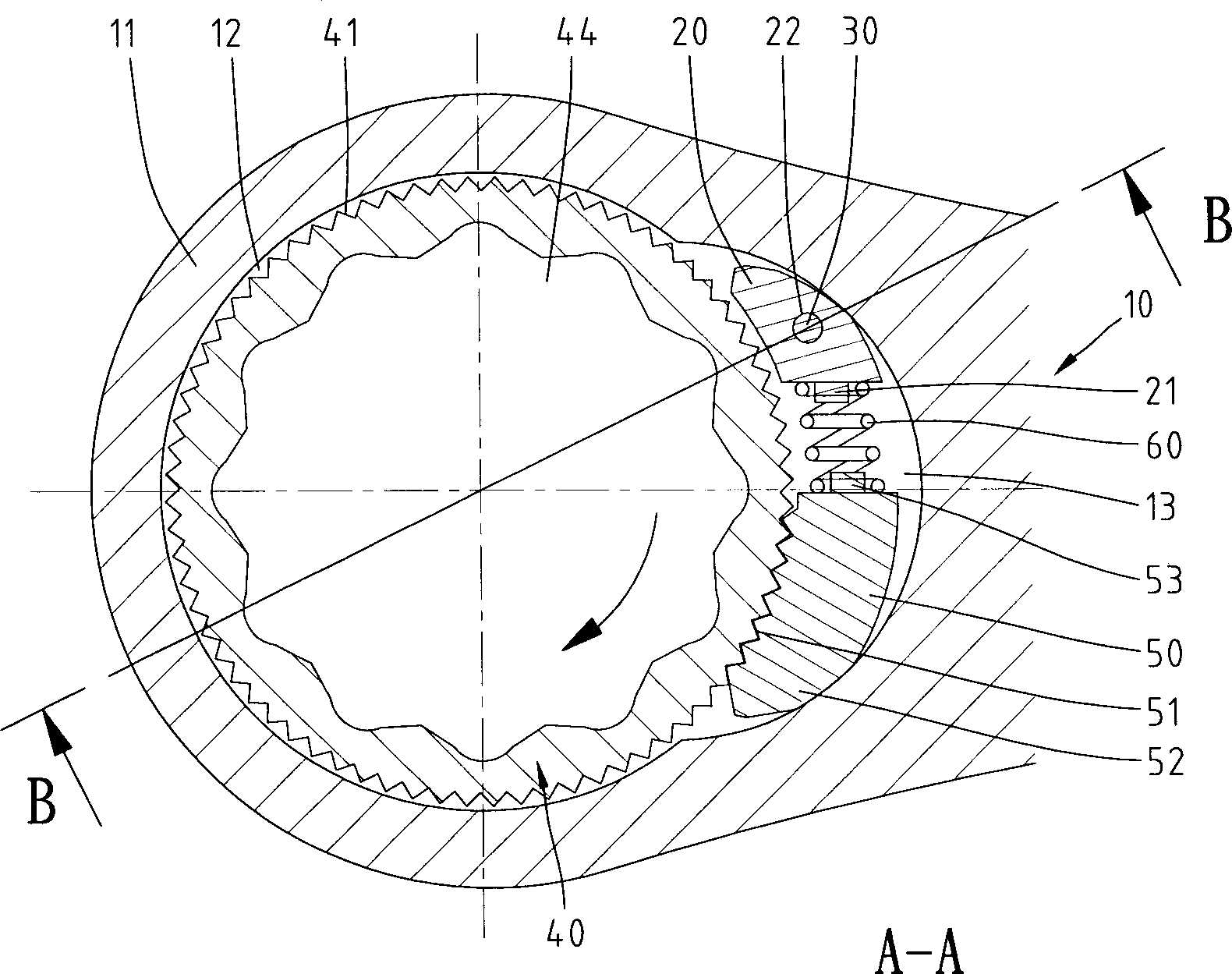
[0051] Please refer to the wrench shown in Figure 2, a ratchet wrench with anti-jamming and marking of the present invention, which includes:

[0052] A wrench body 10, the head 11 at one end of the wrench body 10 is provided with a cylindrical hollow accommodating space 12, one end of the inner wall of the accommodating space 12 is provided with a protruding ring 121, and the other end of the inner wall is ringed A concave ring groove 122 is provided, and a half-moon-shaped accommodating groove 13 is provided at the throat of the wrench body 10. The accommodating groove 13 communicates with the accommodating space 12 and is located in the radial area of ​​one edge of the wrench body 10. 14 is longitudinally provided wit...


PUM


Abstract

The ratchet wrench includes a main body with communicated holding slot and holding space as well as a through hole communicated to the holding slot; a clamping block held in the holding slot; a fixedpart in the through hole and the clamping block to limit the clamping block in the holding slot and to form an indicating mark on one side of the main body; a ratchet wheel with several ratchets; a ratchet block with several ratchets on its one end to mesh with those in the ratchet wheel and capable of being set in the holding slot; and an elastomer between the ratchet block and the clamping block. The turning direction of the wrench can be known via the mark and the ratchet block may be made to separate from the ratchet wheel via pushing the clamping block to prevent jamming.

Description

technical field [0001] The invention relates to the field of hand tools, in particular to a ratchet wrench with anti-jamming and marking functions. Background technique [0002] As we all know, the related industries of hand tools have a long history of development, so the current development space is quite limited, and the survival of the industry is facing challenges. Therefore, only continuous development and innovation can survive, so we can continue to use various Combining forms with various appliances, new forms are produced to increase the added value of products and effectively reduce costs. In a field with limited development space, how to maintain competitiveness is an element that is desperately awaiting breakthroughs in the industry today. [0003] For the traditional ratchet wrench with one-way locking, the user generally cannot know the direction of the wrench's turning, and it is easy to turn the wrench in the wrong direction during operation and use, so the ...

Claims


Application Information

Patent Timeline
IPC IPC(8): B25B13/46
CPCB25B13/463
Inventor 林彦文
Owner 林彦文
Why Eureka
Try Eureka