
A spiral heat exchanger

A heat exchanger, spiral technology, applied in the field of using radially extending rods, can solve the problem of central axis deviation of heat exchangers, etc.

Inactive Publication Date: 2002-10-16
ALFA LAVAL CORP AB
View PDF7 Cites 5 Cited by
  • Summary
  • Abstract
  • Description
  • Claims
  • Application Information

AI Technical Summary

Problems solved by technology

However, from this text it is known that the inlet and outlet flow paths are offset relative to the central axis of the heat exchanger
Furthermore, the design disclosed in EP 214 589 is not suitable for high pressure fluid

Method used


Image

  • A spiral heat exchanger
  • A spiral heat exchanger
  • A spiral heat exchanger

Examples


Embodiment Construction

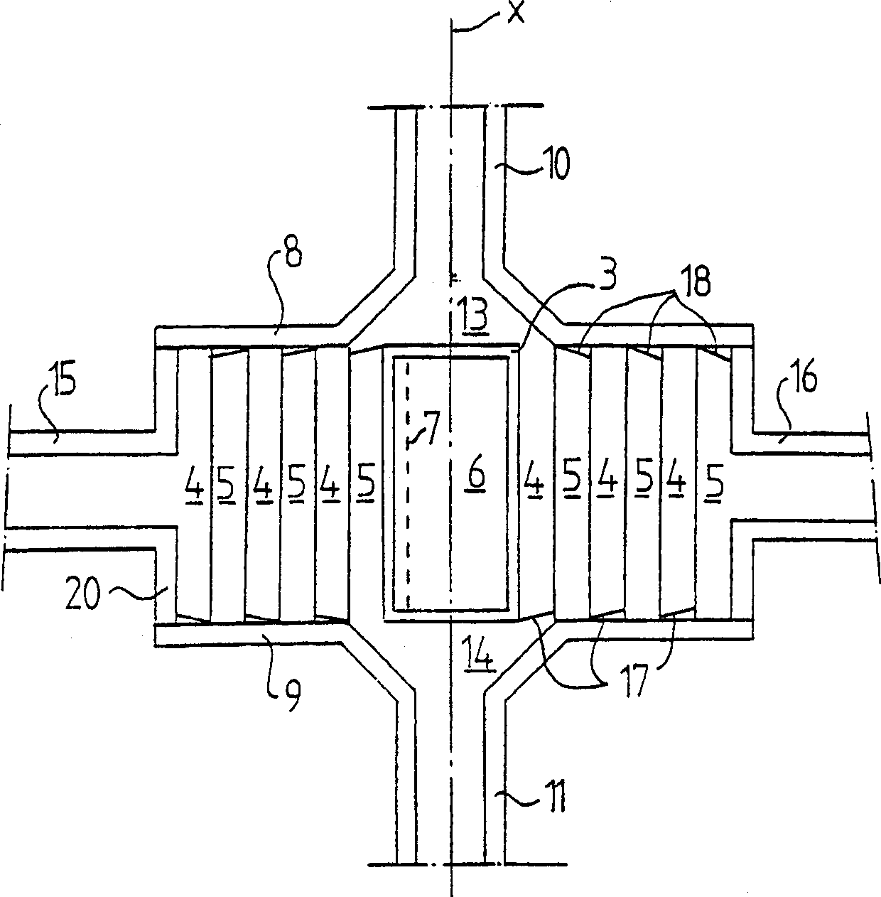
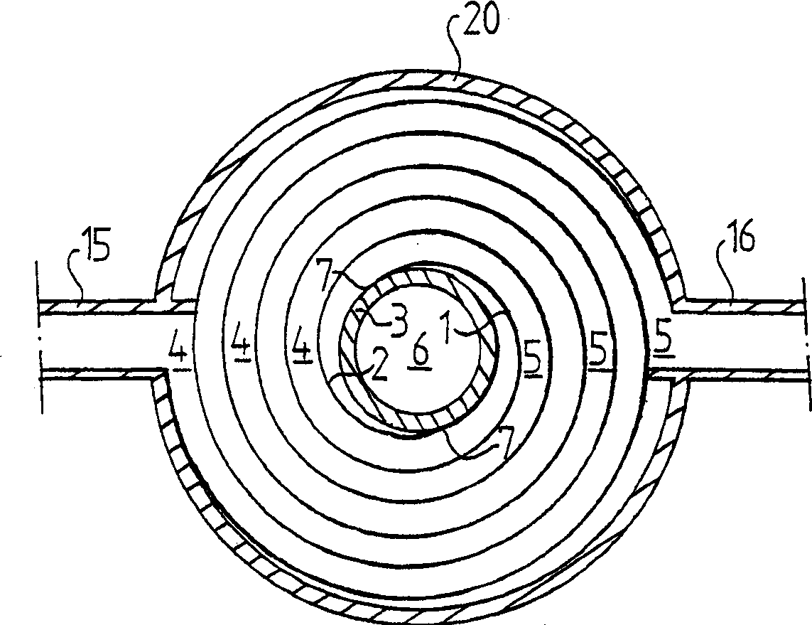
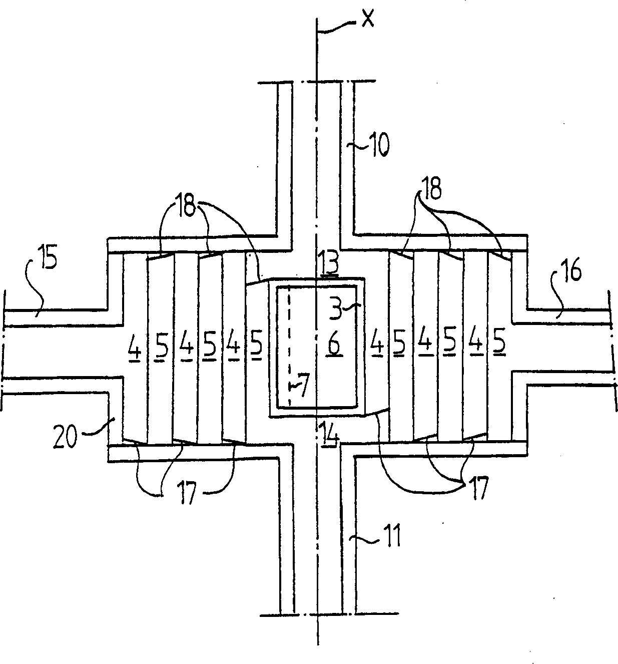
[0023] figure 1 and 2 A first embodiment of the helical heat exchanger of the present invention is schematically shown. The heat exchanger comprises two helical metal plates 1, 2 extending along respective helical paths around a common central axis x. The two helical metal plates 1, 2 are each connected to the central body 3 along a line 7 that is approximately parallel to the central axis x. from figure 2 It can be seen that the lines 7 are positioned diagonally opposite each other with respect to the central axis x. The central body 3 is cylindrical, its outer surface is continuous, and the outer surfaces are connected with spiral plates 1 and 2. The two helical metal plates 1, 2 can be welded to the central body 3 along lines 7, respectively, but other joining methods can also be used.

[0024] The two helical metal plates 1, 2 form two helical flow channels 4, 5 that are parallel to each other. The heat exchange fluid can flow in each flow channel in a direction tan...


PUM


Abstract

The invention relates to a spiral heat exchanger including at least two spiral sheets (1, 2) extending along a respective spiral-shaped path about a common center axis (x) and forming at least two spiral-shaped, substantially parallel flow channels (4, 5). Each flow channel (4, 5) permits a heat exchange fluid to flow in a substantially tangential direction with respect to the center axis (x). Each flow channel includes a radially outer orifice, which forms an outlet or an inlet of the respective flow channel and which is located at a radially outer part of the respective flow channel and a radially inner orifice, which enables communication between the respective flow channel and a respective inlet / outlet chamber (13, 14). The center axis (x) extends through the inlet / outlet chamber of the radially inner orifice. The spiral heat exchanger includes a center body (3) extending around the center axis (x) and being closed with respect to the flow channels (4, 5).

Description

Background technique [0001] The present invention relates to a helical heat exchanger comprising at least two helical plates extending along respective helical paths about a common central axis and forming at least two mutually substantially parallel helical flow passages, wherein, Each flow channel includes a radially outer orifice that places the corresponding flow channel in communication with the corresponding outlet / inlet conduit and the radially outer orifice is located in the corresponding flow channel with respect to the central axis The radially outer portion of the radially inner orifice places the respective flow passages in communication with the respective inlet / outlet chambers so that each flow passage is available for heat exchange fluid flow in a direction generally tangential relative to the central axis, where the central axis Extends through the aforementioned inlet / outlet chamber at the radially inner orifice. [0002] A helical heat exchanger of this type...

Claims


Application Information

Patent Timeline
Patent Type & Authority Applications(China)
IPC IPC(8): F28D9/04
CPCF28D9/04
Inventor O·福特P·毛佩蒂特
Owner ALFA LAVAL CORP AB
Learn More