Anti-theft lock for motor vehicle hand brake
A technology of anti-theft locks and motor vehicles, which is applied to vehicle parts, anti-theft vehicle accessories, transportation and packaging, etc., can solve the problems of expensive anti-theft systems, theft of motor vehicles, and damage to anti-theft systems, and achieve an overall anti-theft effect. Prevent accidental release and low cost effect
- Summary
- Abstract
- Description
- Claims
- Application Information
AI Technical Summary
Problems solved by technology
Method used
Image

Examples
Embodiment 1
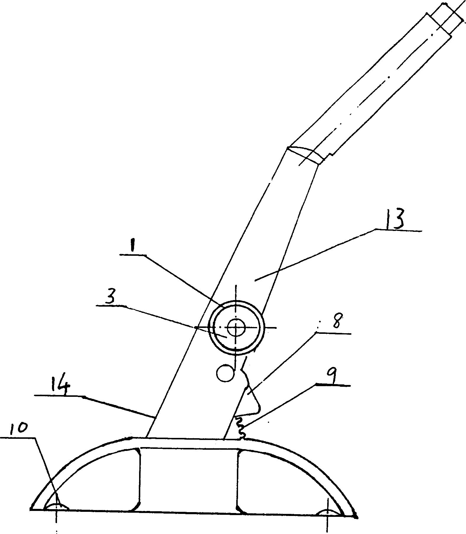
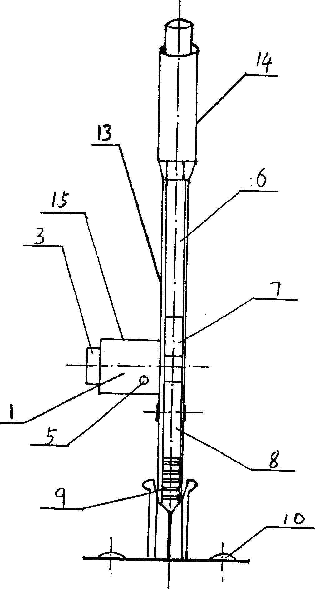
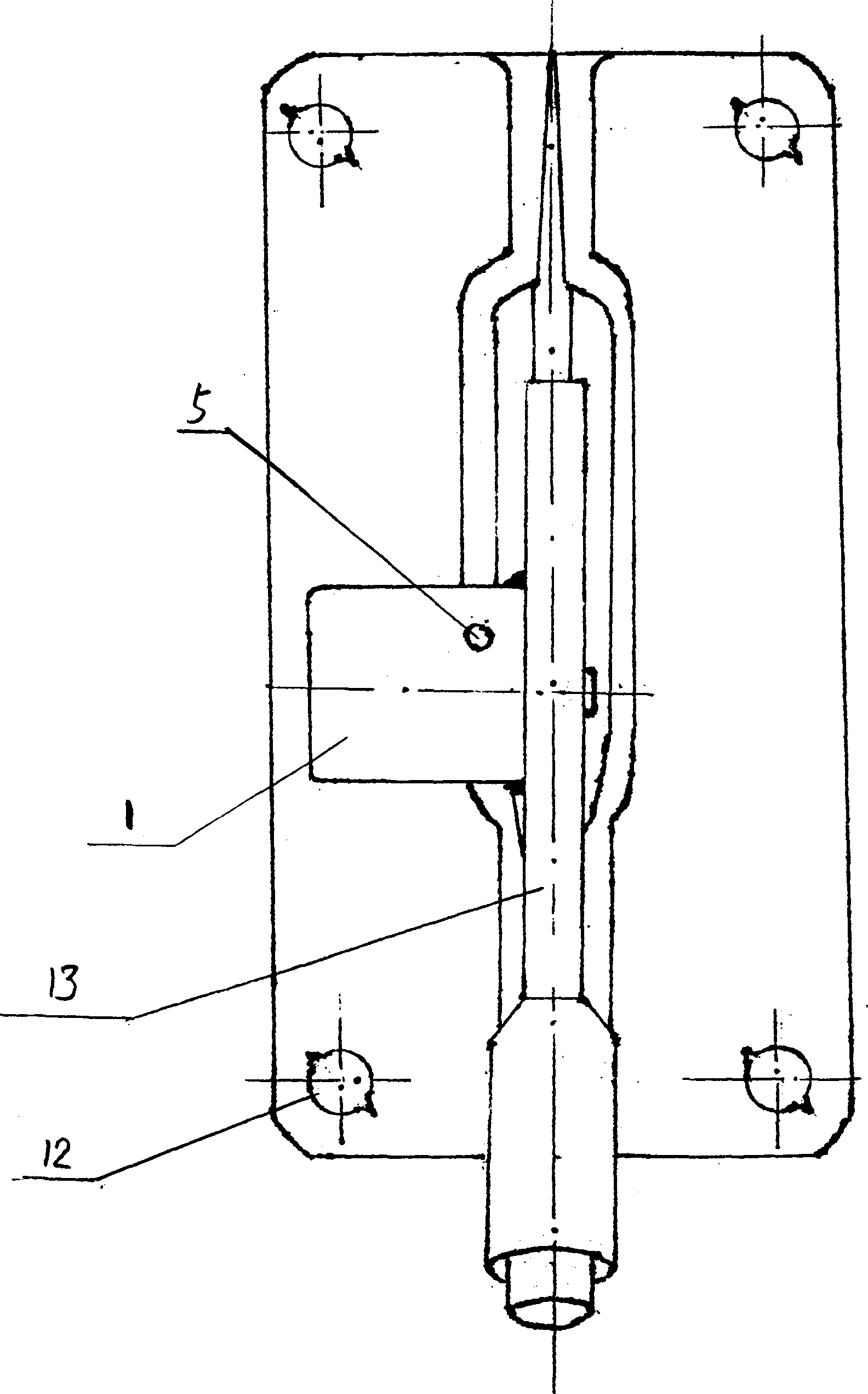
[0016] Embodiment 1, as shown in the figure, the present invention comprises motor vehicle handbrake mechanism 14, is provided with block block 7 on the ejector rod 6 of handbrake mechanism 14, and block block is triangular iron, also can be rectangle, arc block or other shapes, in Two symmetrical locking holes 11 corresponding to the blocking block 7 are opened on both sides of the ejector rod cover 13 of the handbrake mechanism 14. The upper edge of the locking hole 11 is at the same level as the lower edge of the blocking block. One side lock hole is provided with anti-theft lock overcoat 1, is provided with anti-theft lock 15 movablely in anti-theft lock overcoat 1, and this anti-theft lock 15 should adopt the lock cylinder 3 that is used for controlling the brake pad that motorcycle or automobile use, lock There is a lock shell 2 outside the core 3, and the anti-theft lock overcoat 1 is welded on the mandrel cover 13. The anti-theft lock 15 is provided with a telescopic l...
Embodiment 2
[0018] Embodiment 2, as shown in the figure, the present invention includes a motor vehicle hand brake mechanism 14, and a block 7 is arranged on the push rod 6 of the hand brake mechanism 14, wherein the block is formed by the natural bending of the push rod at a suitable position, and its bending The protruding part is the blocking block, and two symmetrical lock holes 11 corresponding to the blocking block 7 are opened on both sides of the mandrel cover 13 of the handbrake mechanism 14, and the upper edge of the locking hole 11 is at the lower edge of the blocking block. On the same level, an anti-theft lock overcoat 1 is arranged on the keyhole on one side of the mandrel cover 13, and an anti-theft lock 15 is movable in the anti-theft lock overcoat 1. The lock core 3 of the lock of brake disc, lock shell 2 is arranged outside lock core 3, and antitheft lock overcoat 1 is to be welded on the mandrel outer cover 13. The anti-theft lock 15 is provided with a telescopic lock b...
Embodiment 3
[0020] Embodiment 3, as shown in the figure, the present invention includes a motor vehicle hand brake mechanism 14, and a block 7 is arranged on the push rod 6 of the hand brake mechanism 14, wherein the push rod is a strip-shaped steel plate, and is provided at a suitable position of the push rod There is a limit hole, which acts as a block, and the upper edge of the hole of the limit hole is a block. On both sides of the mandrel cover 13 of the handbrake mechanism 14, there are corresponding blocks 7. Two symmetrical keyholes 11, the upper edge of the keyhole 11 is at the same level as the lower edge of the blocking block, an anti-theft lock overcoat 1 is arranged on the keyhole on one side of the mandrel cover 13, and the anti-theft lock overcoat 1 is movable Anti-theft lock 15 is arranged, and this anti-theft lock 15 should adopt the lock core 3 that is used for controlling the brake pad that motorcycle or automobile use, and lock shell 2 is arranged outside lock core 3, a...
PUM
 Abstract
Description
Claims
Application Information
 - R&D
- Intellectual Property
- Life Sciences
- Materials
- Tech Scout
- Unparalleled Data Quality
- Higher Quality Content
- 60% Fewer Hallucinations
Browse by: Latest US Patents, China's latest patents, Technical Efficacy Thesaurus, Application Domain, Technology Topic, Popular Technical Reports.
© 2025 PatSnap. All rights reserved.Legal|Privacy policy|Modern Slavery Act Transparency Statement|Sitemap|About US| Contact US: help@patsnap.com