Valve assembly for compressor

A valve assembly and compressor technology, applied in the directions of engine components, control valves, valve devices, etc., can solve the problems that the discharge valves 43 cannot contact each other and the discharge valves 43 cannot operate stably, and achieve the effect of noise reduction.

Inactive Publication Date: 2003-01-29
SAMSUNG GWANGJU ELECTRONICS CO LTD
View PDF0 Cites 6 Cited by
  • Summary
  • Abstract
  • Description
  • Claims
  • Application Information

AI Technical Summary

Problems solved by technology

[0009] In addition, according to the conventional valve assembly 40, if the underside of the fixed end 44a of the retaining plate 44 is uneven, the discharge valve 43 and the retaining plate 44 cannot contact each other at the connecting portion.
If the discharge valve 43 and the holding plate 44 are not in contact at the connecting portion, the lift L of the discharge valve 43 cannot be maintained uniformly, whereby the discharge valve 43 cannot operate stably

Method used


Image

  • Valve assembly for compressor
  • Valve assembly for compressor
  • Valve assembly for compressor

Examples


Embodiment Construction

[0022] Preferred embodiments of the present invention will be described in detail below in conjunction with the accompanying drawings. However, the same reference numerals denote the same parts as those of the conventional compressor, and corresponding descriptions are omitted.

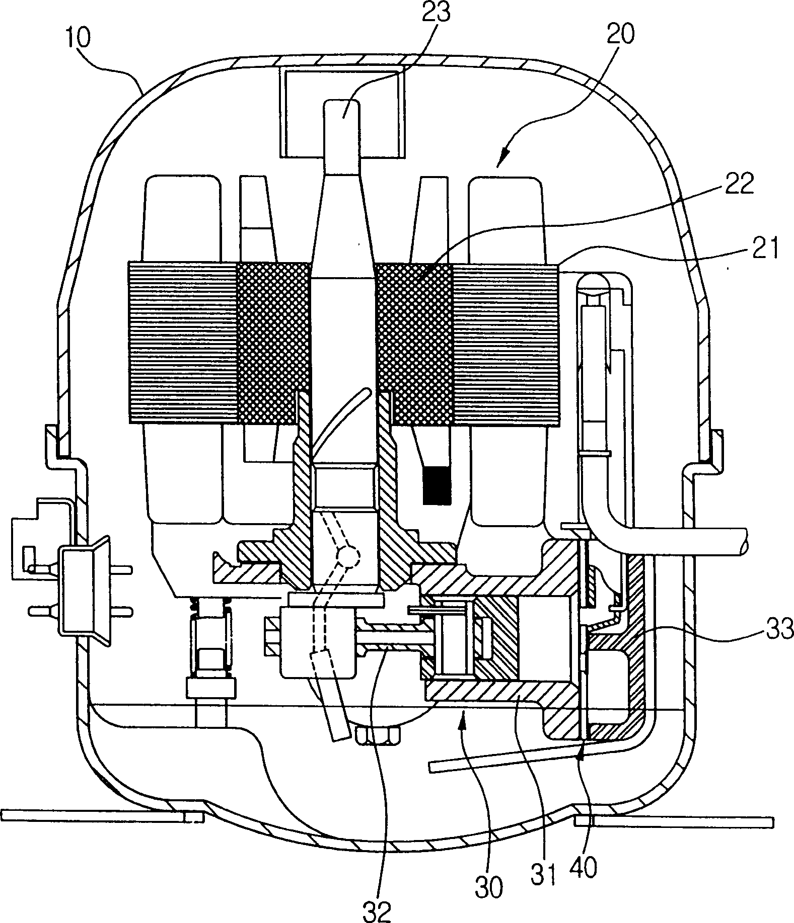
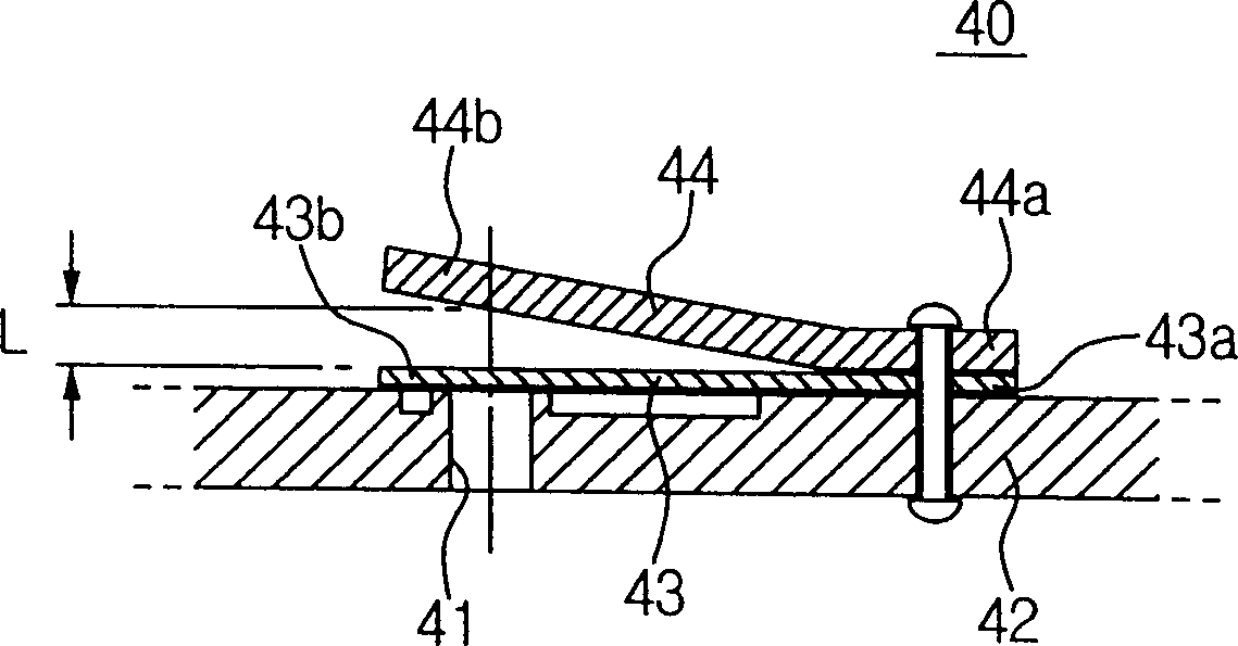
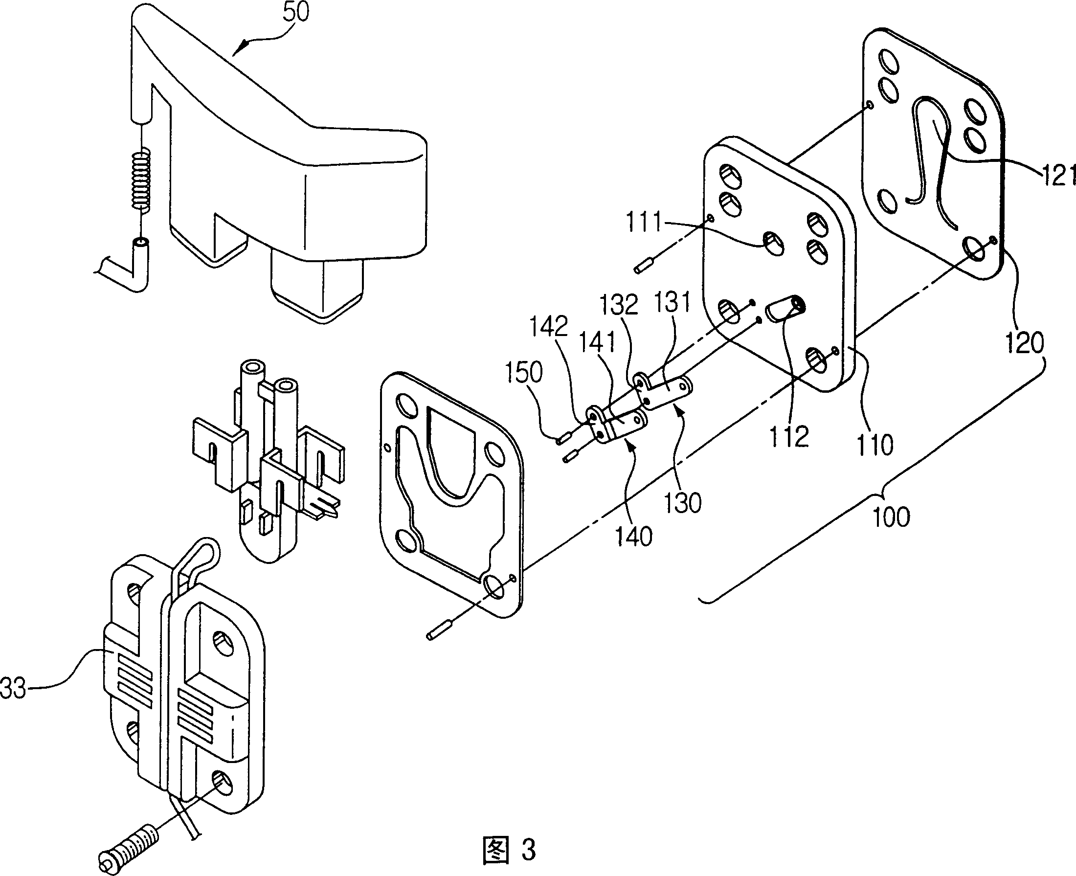
[0023] As shown in Figure 3, the valve assembly 100 of the present invention includes a valve plate 110 having a refrigerant suction hole 11 and a refrigerant discharge hole 112, and a suction valve plate 120 with a suction valve 121, which is arranged on the valve plate 110 and the cylinder (refer to figure 1 31) is used to open or close the refrigerant suction hole 111, the discharge valve 130 located between the valve plate 110 and the cylinder head 33 is used to open or close the refrigerant discharge hole 112, and is arranged on the discharge valve The retaining plate 140 on the upper part of 130 is used to control the opening range of the discharge valve 130 .

[0024] The discharge valve 130 i...


PUM


Abstract

The valve assembly includes a valve plate having a refrigerant discharging hole, a discharging valve having one end that is settled at the valve plate for opening and closing the refrigerant discharging hole, a keeper, placed at above the discharging valve, having one end that is connected with the valve plate with the discharging valve for limiting lift of the discharging valve, and a bead protruded for a predetermined width W and height H at a lower side of the keeper. The lift L of the discharging valve can be maintained evenly, since the bead compresses an upper side of the discharging valve. Moreover, the discharging valve is firmly settled at the valve plate. Accordingly, abnormal noise generated when refrigerant is discharged can be reduced because the discharging valve operates with stability.

Description

technical field [0001] The invention relates to a valve assembly of a compressor, in particular to a valve assembly capable of reducing abnormal noise when discharging refrigerant. Background technique [0002] Compressors are generally widely used in refrigeration equipment such as refrigerators that compress refrigerant. [0003] Such as figure 1 As shown, a conventional reciprocating compressor includes a drive unit 20 with a stator 21 and a rotor 22 inside a housing 10, and a compression unit 30, which is used to extract the extracted The refrigerant is discharged, and the crankshaft 23 is inserted into the center portion of the rotor 22 by pressing. [0004] The compression unit 30 includes a cylinder 31 and a piston 32 reciprocating inside the cylinder 31 to compress refrigerant. A cylinder head 33 for sealing the cylinder 31 is provided at the front of the cylinder 31 . In addition, a valve assembly 40 for supplying refrigerant into the cylinder 31 or discharging ...

Claims


Application Information

Patent Timeline
Patent Type & Authority Applications(China)
IPC IPC(8): F04B39/10F16K15/03F16K15/16
CPCF16K15/16F04B39/1073F16K15/031Y10T137/7892F04B39/10F16K15/162
Inventor 林镐祥
Owner SAMSUNG GWANGJU ELECTRONICS CO LTD
Why Eureka
Try Eureka