

Negative pressure leakage proofing device for ink cartridge
A leak-proof device and ink cartridge technology, applied in printing and other directions, can solve problems such as affecting product printing and quality, inability to accurately control the negative pressure setting range, and changing the magnetic force of metal valve seats and valves.
- Summary
- Abstract
- Description
- Claims
- Application Information
AI Technical Summary
Problems solved by technology
Method used
Image

Examples
no. 1 example
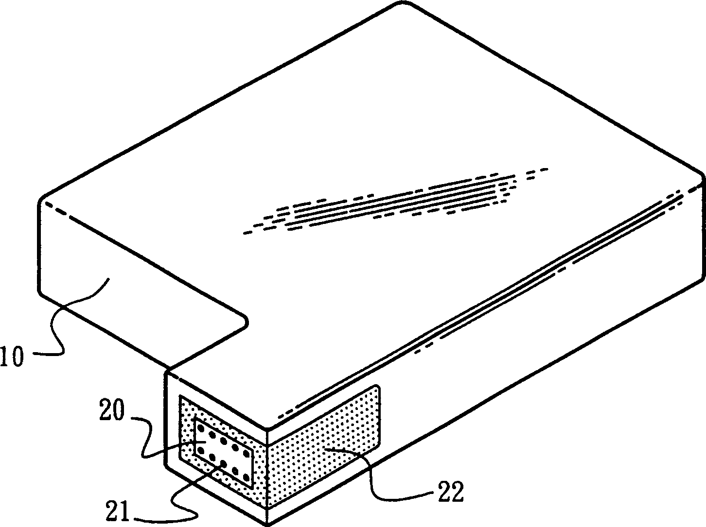
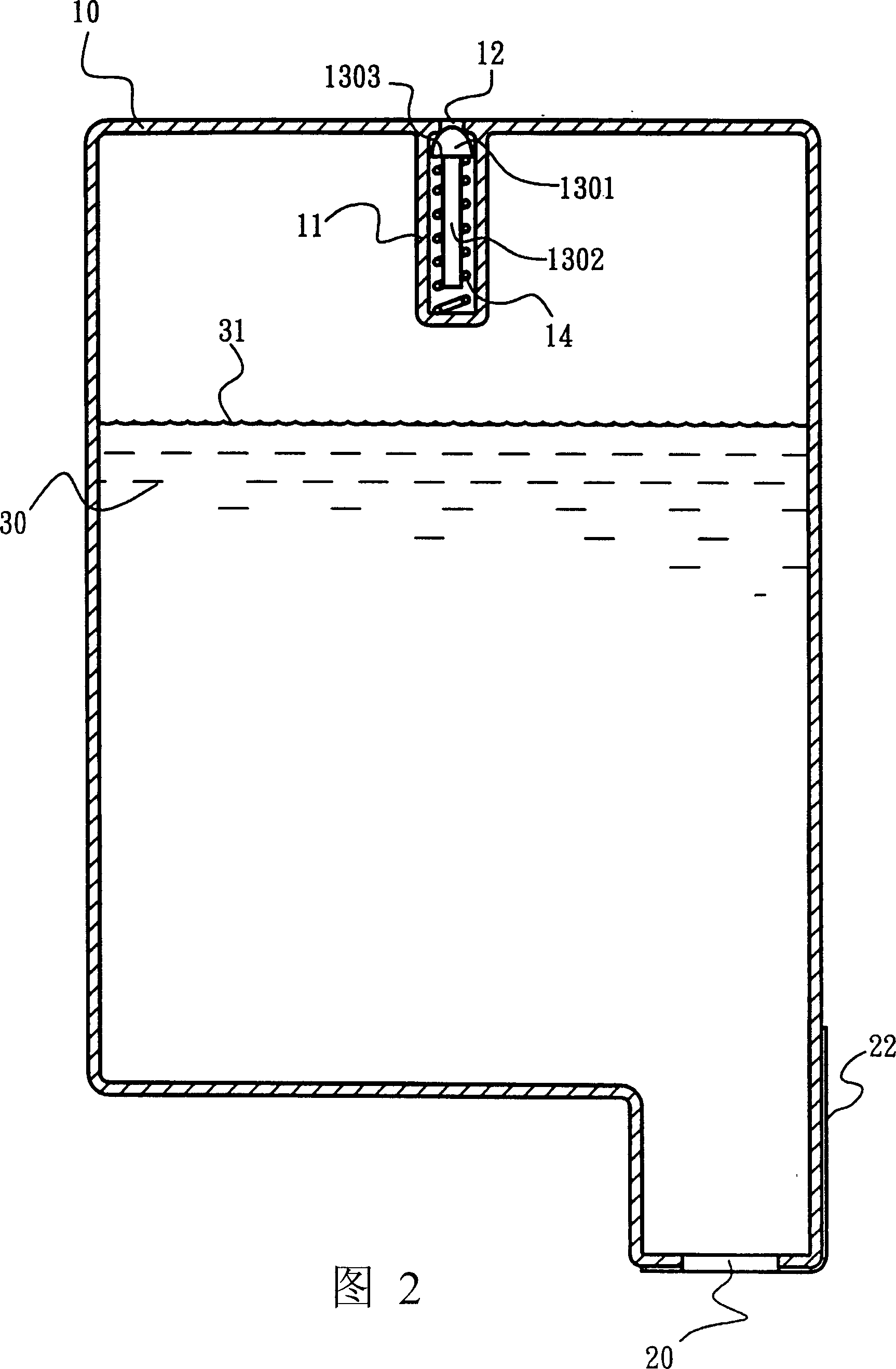
[0029] As shown in FIG. 2 , according to a specific embodiment of the present invention, a vent hole 12 is provided on one side of the ink cartridge 10 , and a fixing seat 11 , a thimble 13 and a coil spring 14 are provided inside. The fixing seat 11 communicates with the air hole 12 and can accommodate the thimble 13 and the coil spring 14 . The thimble 13 has a conical or egg-head-shaped surface 1301, which can be in close contact with the edge of the air hole 12 and completely cut off the passage of air. A needle bar 1302 is connected to the conical surface or egg-head-shaped surface 1301, which can wear a helical spring 14, and pushes the flange 1303 below the egg-head-shaped surface 1301 by the helical spring 14, so that the conical surface or egg-head-shaped surface 1301 can be made The surface 1301 is biased against the vent hole 12 so that the ink cartridge 10 is completely airtight.
[0030] The purpose of sealing the vent hole 12 is to cut off the path of outside ai...
no. 2 example
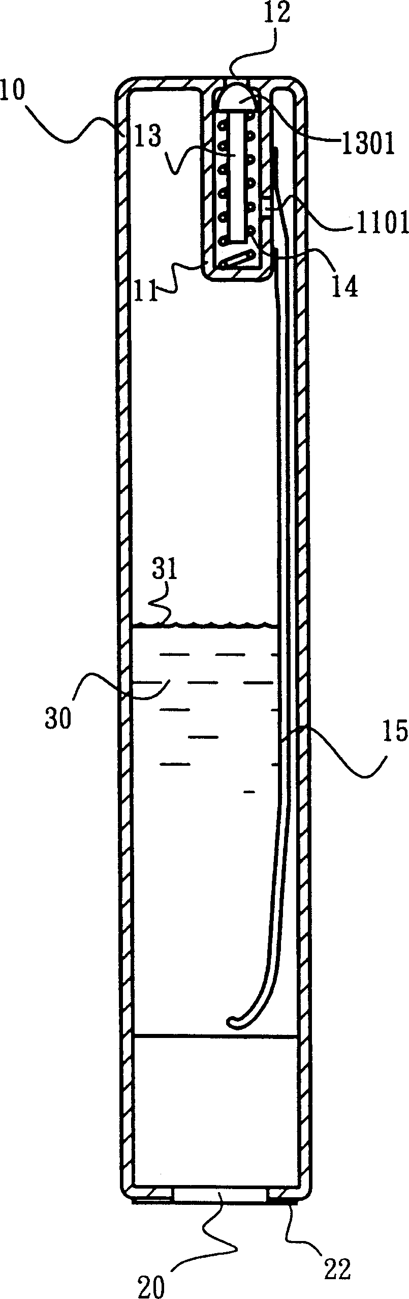
[0032] Ideally, it can be rewritten as image 3 Modification changes shown. An air bag 15 is added to the structure of the aforementioned first embodiment, and an air hole 1101 is set on the fixing seat 11 to communicate with the air bag 15 .
[0033] Such as image 3 As shown, in an inkjet operation, the ink level 31 gradually decreases as the inkjet printing progresses, and the negative pressure in the cartridge gradually increases accordingly. However, within an operable negative pressure range, the force exerted by the coil spring 14 on the thimble 13 is always greater than the force exerted by the external atmospheric pressure on the conical surface or the egg-head-shaped surface 1301, so the ink cartridge 10 can continue to remain airtight.
[0034] Such as Figure 4 As shown, when the negative pressure that continues to be generated in the box has reached a limit value, the force of the atmospheric pressure acting on the conical surface or the egg-head-shaped surface...
no. 3 example
[0036] As shown in FIG. 5 , according to the present invention, if the components are further simplified, the needle shaft 1302 of the thimble 13 is omitted, and its conical or egg-head-shaped surface 1301 is retained to abut against the air hole 12 , which is also a feasible implementation. With the support of a thin plate spring or shrapnel 16 , the conical or egg-shaped surface 1301 tends to abut against the air hole 12 . As shown in Figure 6, with the aforementioned principle, when the negative pressure that continues to be generated in the box has reached a limit value, the force of the atmospheric pressure acting on the conical surface or the egg-head-shaped surface 1301 exceeds that of the thin plate spring or shrapnel 16 applied to the thimble 13. The force makes the conical surface or the egg head-shaped surface 1301 shrink back, and the trace air from the outside will enter the air bag 15 in the ink cartridge 10, and the air bag 15 will expand, so that the ink liquid ...
PUM
 Abstract
Description
Claims
Application Information