Multigang switchgear

A technology of switching devices and switching elements, which is applied in the direction of electric switches, electrical components, contact engagement, etc., and can solve problems such as complicated operation, unstable switching action of switching elements, and time-consuming

Inactive Publication Date: 2003-03-12
ALPS ALPINE CO LTD
View PDF0 Cites 3 Cited by
  • Summary
  • Abstract
  • Description
  • Claims
  • Application Information

AI Technical Summary

Problems solved by technology

[0007] However, in the above-mentioned conventional multiple switch device, the bending portion of each movable contact 46 is inserted between the partition wall 45 and the supporting protrusion 44, and the movable contact 49 is installed in the case 41 by a plurality of operations. The operation in the slit between the body 42 and the partition wall 45 is extremely complicated, thus

Method used


Image

  • Multigang switchgear
  • Multigang switchgear
  • Multigang switchgear

Examples


Embodiment Construction

[0030] Embodiment of the invention

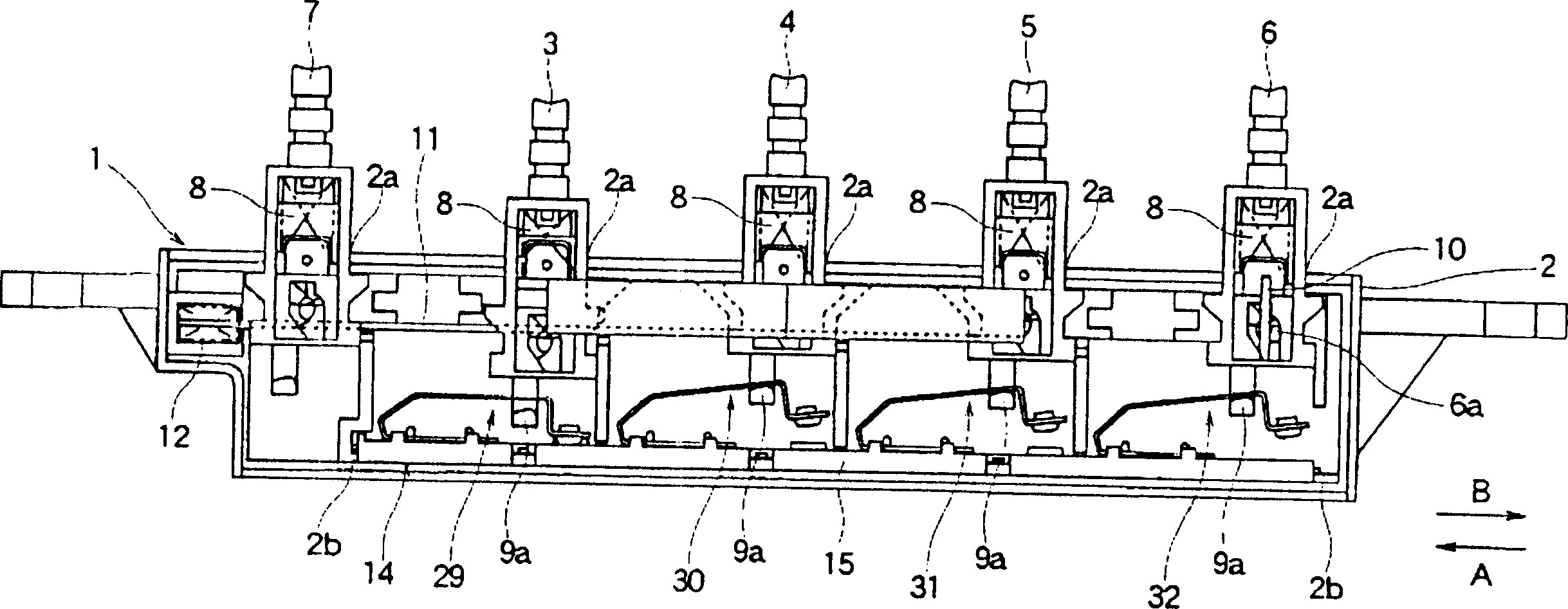
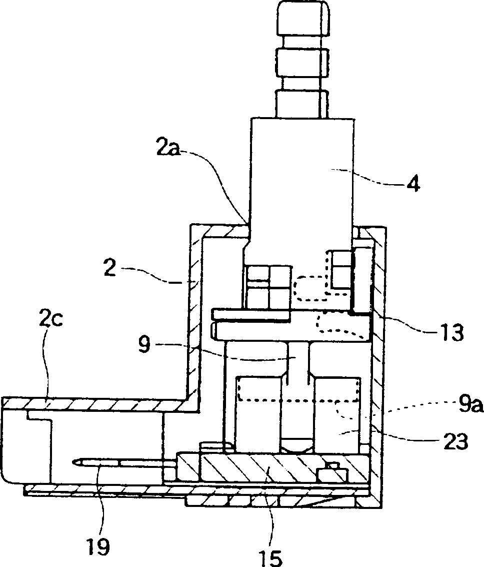
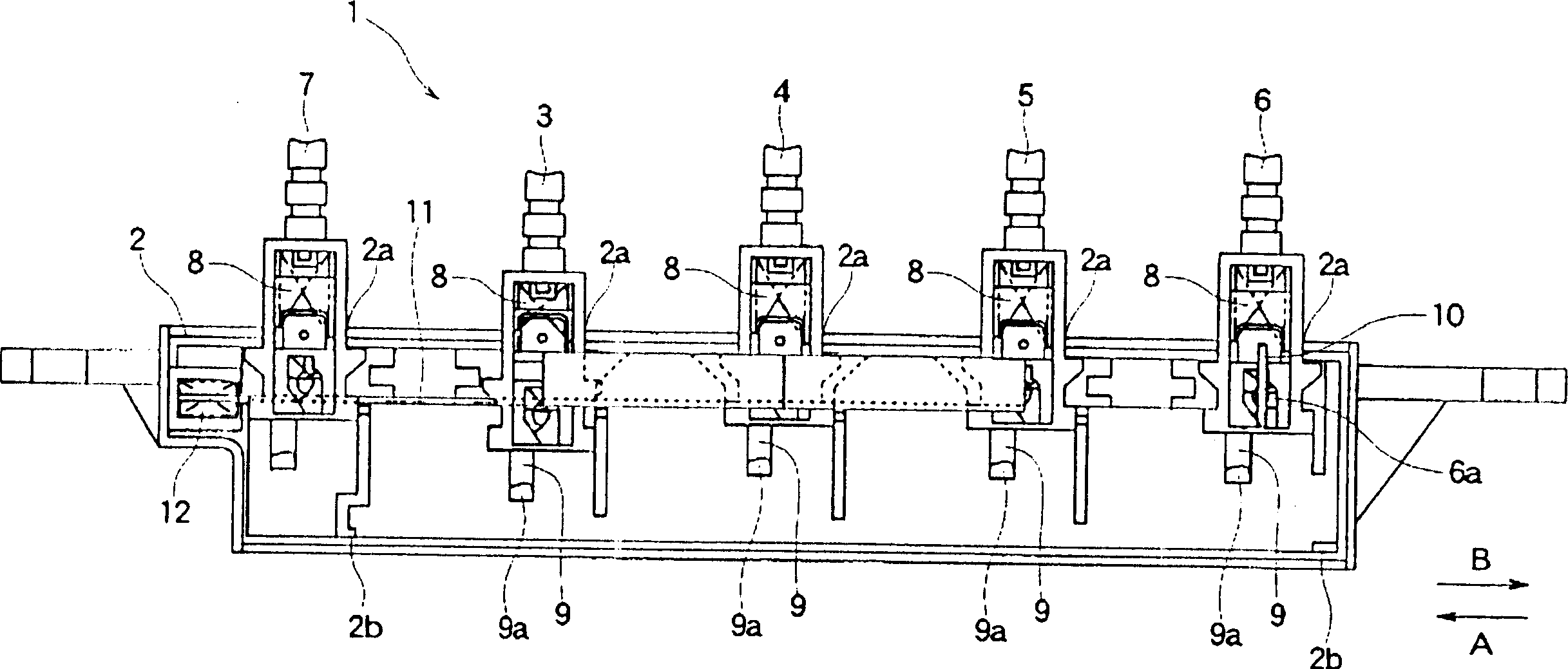
[0031] An embodiment of the multi-connector switch device of the present invention will be described below with reference to the accompanying drawings. Figure 1 to Figure 11 is to describe an embodiment of the present invention, figure 1 It is a side view seen from one side after the cover body of the multi-connection switch device according to an embodiment of the present invention is removed, figure 2 It is a transverse sectional view of the multi-connection switch device.

[0032] The main structure of the multi-switch device shown in the above two figures includes: an operating mechanism part 1, a long box-shaped housing 2 with an open side, and an operating body 3 installed in the housing 2 so that it can move up and down freely. , 4, 5, 6; the switch mechanism part 14 has a plurality of switch units 29, 30, 31, 32 that respectively perform switch actions through the up and down movement of each operating body 3, 4, 5, 6; wherein ...


PUM


Abstract

The invention provides a multiple switch device capable of providing an excellent assemblability and a stable switching operation. This multiple switch device comprises an operating mechanism part 1 having a casing 2 and a plurality of operating bodies 3 to 6 held on the casing 2 movably in vertical direction and a switch mechanism part 14 having a plurality of switch elements 29 to 32 for performing a switching operation by the vertical movement of the operating bodies 3 to 6, a plurality of terminals 16 to 21 for connecting the plurality of switch elements 29 to 32 to external equipment, and a base stand 15 supporting the plurality of switch elements 29 to 32 and the plurality of terminals 16 to 21. The operating mechanism part 1 and the switch mechanism part 14 are formed separately from each other, and the base stand 15 is fixed to the inside of the casing 2 so that the operating mechanism part 1 can be formed integrally with the switch mechanism part 14.

Description

technical field [0001] The invention relates to a multi-connection switch device, in particular to a multi-connection switch device suitable for the operation part of a ventilation cover. Background technique [0002] Figure 5 It is a side view viewed from one side of a known multi-gang switchgear. As shown in this figure, in a box-shaped housing 41 with an open side, a plurality of operating bodies 42 and a reset operating body 43 are set, respectively, by means of the biasing force of the return spring 50. Its upper end protrudes from the opening 41a provided on the upper surface of the casing 41 at a certain interval and is held to move freely up and down, and a plurality of operating bodies 42 and a reset operating body 43 in the casing 41 are respectively provided with a support. Partition walls 45 with protrusions 44 and fixed contacts 46 made of sheet metal. [0003] And, in the housing 41, a joint flat plate 47 combined with the joint protrusions (not shown) forme...

Claims


Application Information

Patent Timeline
IPC IPC(8): H01H13/04H01H1/26H01H9/02H01H9/20H01H11/06H01H13/14H01H13/26H01H13/72
CPCH01H11/06H01H2011/067H01H1/26H01H13/72
Inventor 川濑达章后藤义美
Owner ALPS ALPINE CO LTD
Why Eureka
Try Eureka