Multi-layer LC composite element and mfg. method thereof

A composite component and component technology, applied in the field of multi-layer LC composite components and their manufacturing, can solve the problems of deteriorating high-frequency characteristics, large parasitic capacitance, etc.

Inactive Publication Date: 2003-03-12
MURATA MFG CO LTD
View PDF0 Cites 18 Cited by
  • Summary
  • Abstract
  • Description
  • Claims
  • Application Information

AI Technical Summary

Problems solved by technology

[0014] Furthermore, the parasitic capacitance generated between the coil wire 13 and the terminal electrodes 16 to 19, the parasitic capacitance generated between the capacitor electrode 12 and the terminal electrodes 16 to 19, the ground side terminal electrodes 16 and 17 and the charging side terminal electrodes 18 and 19 The parasitic capacitance between becomes relatively large, which deteriorates high-frequency characteristics

Method used


Image

  • Multi-layer LC composite element and mfg. method thereof
  • Multi-layer LC composite element and mfg. method thereof
  • Multi-layer LC composite element and mfg. method thereof

Examples


Embodiment Construction

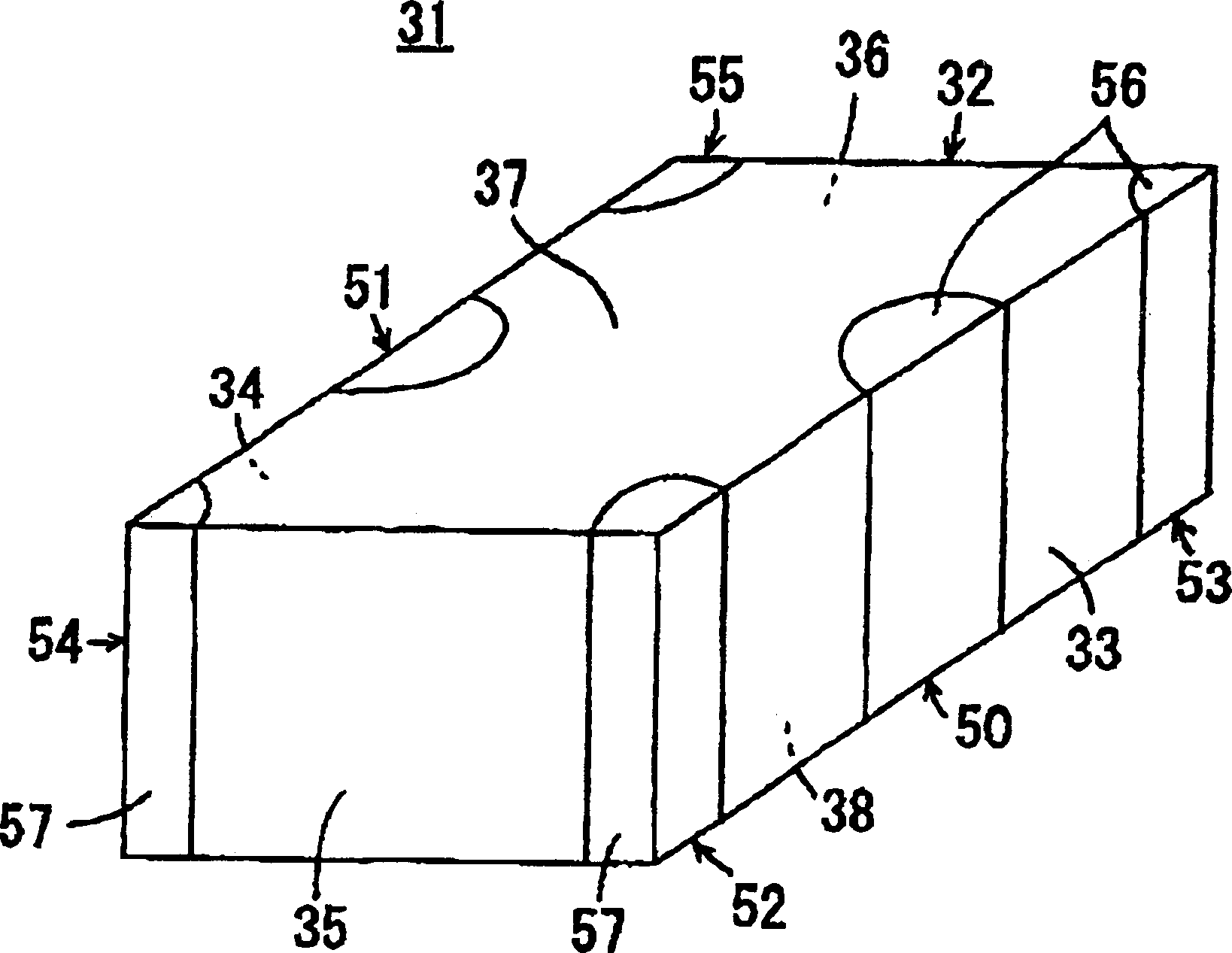
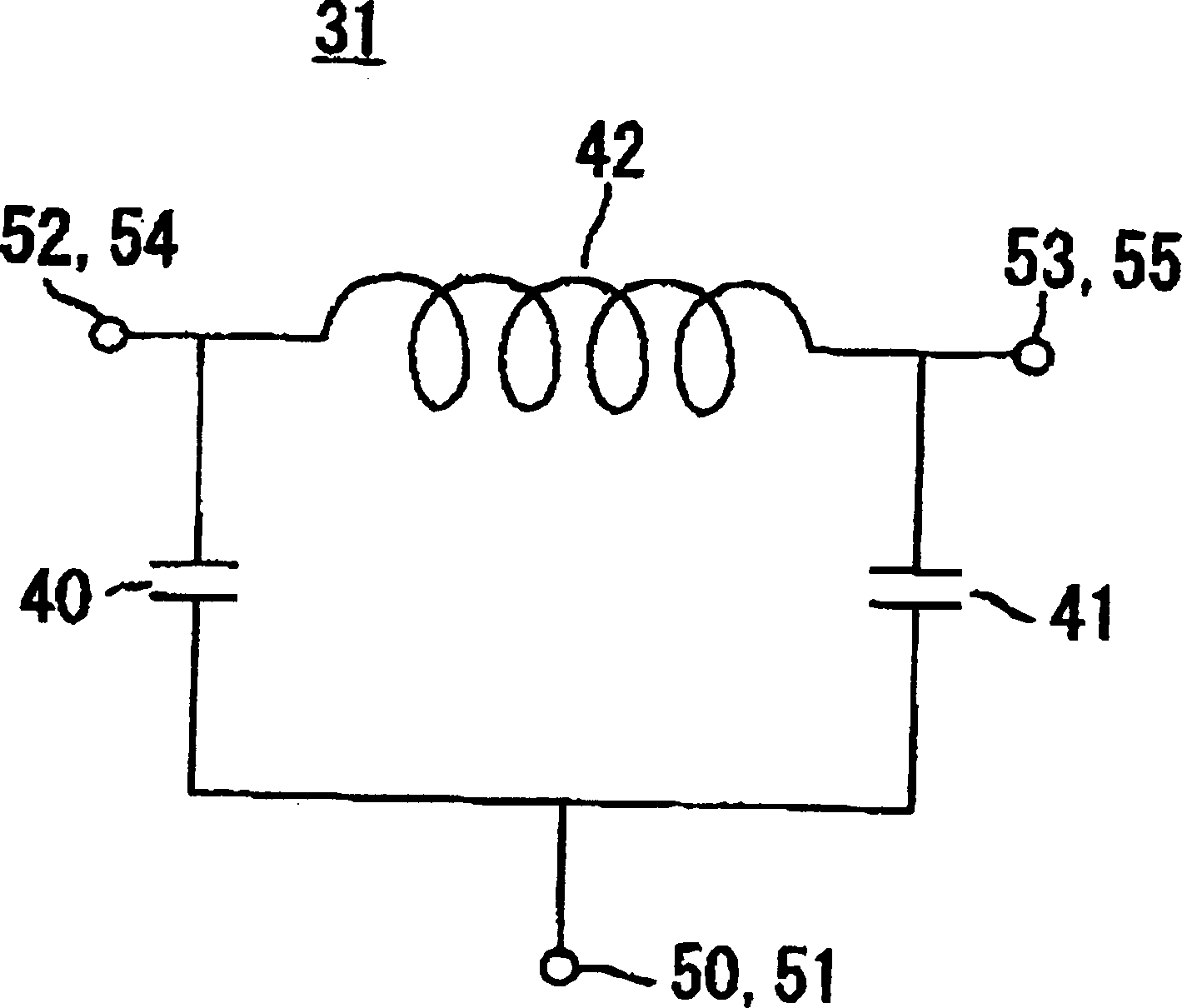
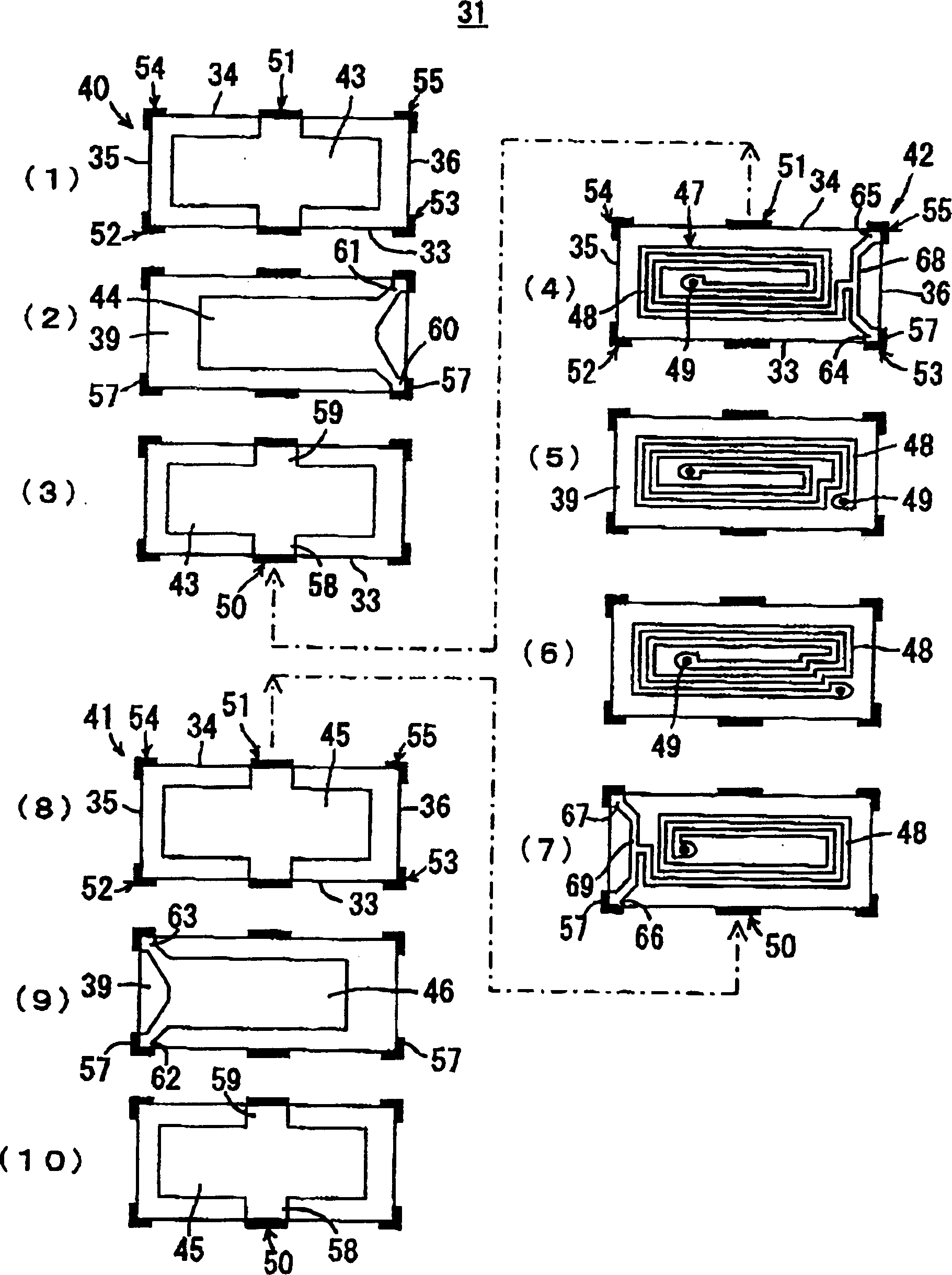
[0042] figure 1 is a perspective view showing the multilayer LC composite element 31 according to the first embodiment of the present invention. figure 2 is as figure 1 The equivalent circuit diagram of the multilayer LC composite element 31 is shown. image 3 Including showing decomposition such as figure 1 A plan view of the multilayer LC composite element 31 is shown.

[0043] The multilayer LC composite element 31 comprises a substantially rectangular body 32 . The main body 32 includes a pair of side surfaces 33 and 34 facing each other, a pair of end surfaces 35 and 36 facing each other, and upper and lower surfaces 37 and 38 facing each other.

[0044] For example, the body 32 is about 1.6 mm long, about 0.8 mm wide, and about 0.6 mm high.

[0045] like image 3 As shown, the body 32 has a multilayer structure including a plurality of electrically insulating layers 39 . The main body 32 includes as image 3 The capacitor element 40 shown in (1) to (3), as ...


PUM

PropertyMeasurementUnit
thicknessaaaaaaaaaa

Abstract

A multilayered LC composite component includes a main body having a pair of side surfaces, a pair of end surfaces, and an upper surface and a lower surface. Ground-side terminal electrodes are disposed at the center of the side surfaces and hot-side terminal electrodes are disposed along edges of the side surfaces. Each of the hot-side terminal electrodes includes an end surface extended portion extending to each of the end surfaces. The end-surface extended portion is arranged so that at least the approximate center of each of the end surfaces is exposed.

Description

technical field [0001] The present invention relates to a multilayer LC composite element and its manufacturing method. Specifically, the present invention relates to an improvement in the layout of terminal electrodes disposed on the outer surface of a device main body. Background technique [0002] Figure 13 is a perspective view showing a known multilayer LC composite element 1 related to the present invention. Figure 14 is displayed as Figure 13 A cross-sectional view of the internal structure of the multilayer LC composite element 1 shown. [0003] The multilayer LC composite element 1 comprises a rectangular body 2 . The main body 2 includes a pair of side surfaces 3 and 4 facing each other, a pair of end surfaces 5 and 6 facing each other, and an upper surface 7 and a lower surface 8 facing each other. [0004] The main body 2 has a multilayer structure including a plurality of electrically insulating layers, and has a capacitor element 10 and an inductor elemen...

Claims


Application Information

Patent Timeline
Patent Type & Authority Applications(China)
IPC IPC(8): H01F27/00H01G4/40H03H7/01H03H7/075H05K1/02H05K3/34
CPCH05K2201/10045H05K1/0243H05K2201/09381H05K3/3442H05K2201/09954H03H7/0115H03H2001/0085Y02P70/50H01G4/40
Inventor 佐佐木友嘉东贵博山本重克
Owner MURATA MFG CO LTD
Why Eureka
Try Eureka