Electric arc preventing method and transitional quencher with the same method

An arc extinguishing device and arc technology, applied in circuits, electrical switches, electrical components, etc., can solve the problems of elongation, difficulty in extinguishing arcs, and unsatisfactory effects, and achieve the effect of reducing contact resistance.

Inactive Publication Date: 2003-03-19
夏利霞
View PDF0 Cites 2 Cited by
  • Summary
  • Abstract
  • Description
  • Claims
  • Application Information

AI Technical Summary

Problems solved by technology

At present, oil immersion cooling, elongation and the use of the zero-crossing point of alternating current are usually used to extinguish the arc, but the effect is not ideal, especially when encountering capacitive or inductive load current and direct current, it is difficult to extinguish the arc

Method used


Image

  • Electric arc preventing method and transitional quencher with the same method
  • Electric arc preventing method and transitional quencher with the same method
  • Electric arc preventing method and transitional quencher with the same method

Examples


Embodiment 1

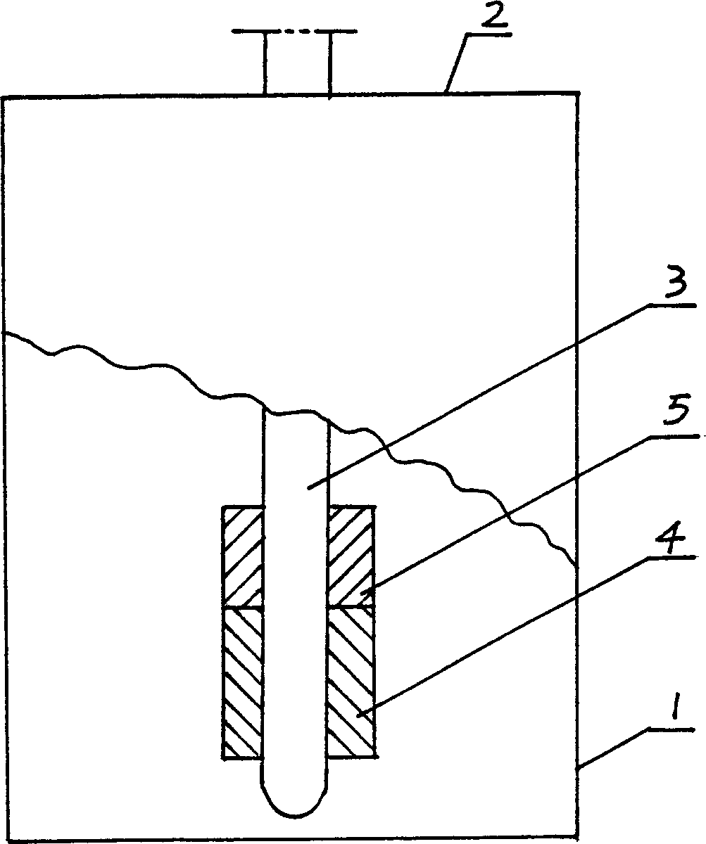
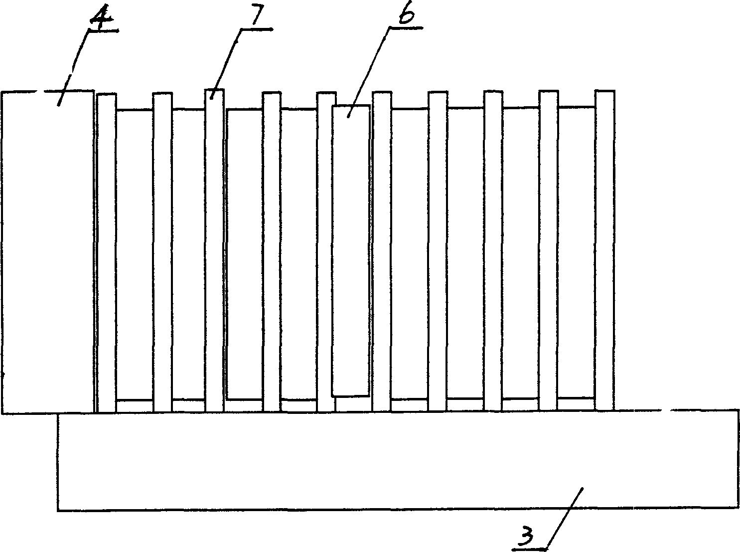
[0020] Embodiment 1: attached figure 1 Shown is a composite resistor extending across the stationary contacts. In the figure, the fuel tank 1 is provided with a fuel tank cover 2, and the movable contact 3 penetrates into the static contact 4, and a composite resistor 5 is extended on the upper part of the static contact 4, where the composite resistor 5 is cylindrical, and the composite resistor 5 is composed of multiple Resistor sheet 6 and equalizer sheet 7 are stacked at intervals (see image 3 ), the diameter of the flow equalizer 7 is longer than that of the resistance sheet 6, and when the moving and static contacts are separated, the flow equalizing sheet 7 is in contact with the moving contact respectively, that is, the compound resistance 5 is connected in series to the switch circuit for shunting, and the moving and static contacts are separated by the resistance sheet When the switch is completely disconnected, the connected resistance is the largest, and the curr...

Embodiment 2

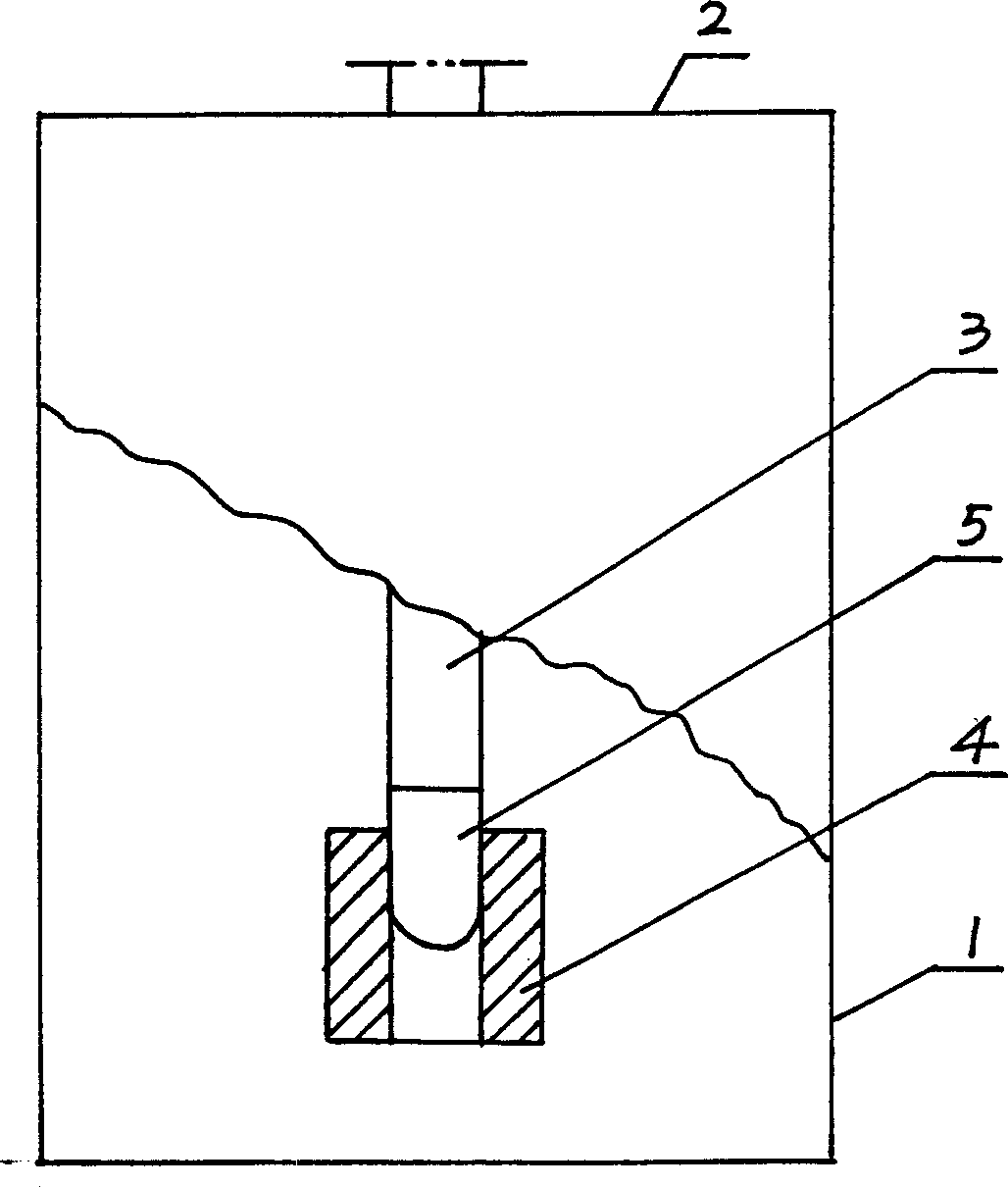
[0021] Embodiment 2: A cylindrical composite resistor 5 is extended on the moving contact 3 . The composite resistor 5 is also formed by stacking a plurality of resistive sheets 6 and current equalizers 7 at intervals. When the dynamic and static contacts are separated, the current equalizers 7 are respectively in contact with the static contacts 4, that is, the composite resistor 5 is connected in series to the switch circuit. Diverting, so as to achieve the purpose of high-efficiency arc extinguishing.

[0022] Both embodiment 1 and embodiment 2 are arc extinguishing by connecting composite resistors in series on the SN1-10 switch

Embodiment 3

[0023] Embodiment 3: see Figure 4 , is to connect the composite resistor in series on the composite switch used in the reactive power compensation cabinet to extinguish the arc. There are multiple static contacts 4 in the figure, and the conductive rod of the present invention is a movable contact 3, on which a composite resistor 5 is extended. A static contact 4, when the static contact 4 is completely disconnected from the movable contact 3, the composite resistor 5 has the largest contact area with the static contact 4, and the resistance is the largest, which can effectively prevent the generation of arc. Resistor 5 is square.


PUM


Abstract

The present invention is electric arc preventing method and transitional quencher for electric power switch. Composite resistor is connected serially in switch circuit and the resistance of the composite resistor become greater gradually after the switch is turned off until the switch is turned off completely. The said method can prevent electric arc produced when the switch is used to turn on or off the load current is changed in connection mode. The present invention may be used widely in various electric power switch.

Description

Technical field: [0001] The invention belongs to the electrical field, and relates to a method for avoiding arc generation when a power switch is disconnected and a device for avoiding arc generation designed according to the method. technical background: [0002] The main function of the power switch working in the power system is to break, connect the load current and change the wiring mode. When the power switch breaks the load current or fault current, a large arc will be generated. The powerful energy of the arc will usually affect the service life of the switch. In severe cases, the switch will explode. Therefore, the method of extinguishing the arc must be adopted inside the power switch. A device for extinguishing an arc. At present, oil immersion cooling, elongation and zero crossing of alternating current are usually used to extinguish the arc, but the effect is not ideal, especially when encountering capacitive or inductive load current and direct current, it is ...

Claims


Application Information

Patent Timeline
Patent Type & Authority Applications(China)
IPC IPC(8): H01H33/16
CPCH01H33/161
Inventor 夏利霞
Owner 夏利霞
Why Eureka
Try Eureka