Spinning devices

A yarn and yarn guide technology, which is applied to spinning machines, jointing devices, free-end spinning machines, etc., can solve the problems of reducing production efficiency, improve success rate, prevent yarn breakage, and increase yarn strength Effect

Inactive Publication Date: 2003-04-02
MURATA MASCH LTD
View PDF1 Cites 18 Cited by
  • Summary
  • Abstract
  • Description
  • Claims
  • Application Information

AI Technical Summary

Problems solved by technology

thus reducing production efficiency

Method used


Image

  • Spinning devices
  • Spinning devices
  • Spinning devices

Examples


Embodiment Construction

[0020] Hereinafter, preferred embodiments of the present invention will be described in detail according to the accompanying drawings.

[0021] Figure 5 It shows a spinning machine 1 with a plurality of spinning components 2 arranged side by side. In this spinning machine 1, a piecing device (piece trolley) 3 installed so as to be able to move freely between spinning members 2, a blow box 4, and a power frame 5 are installed.

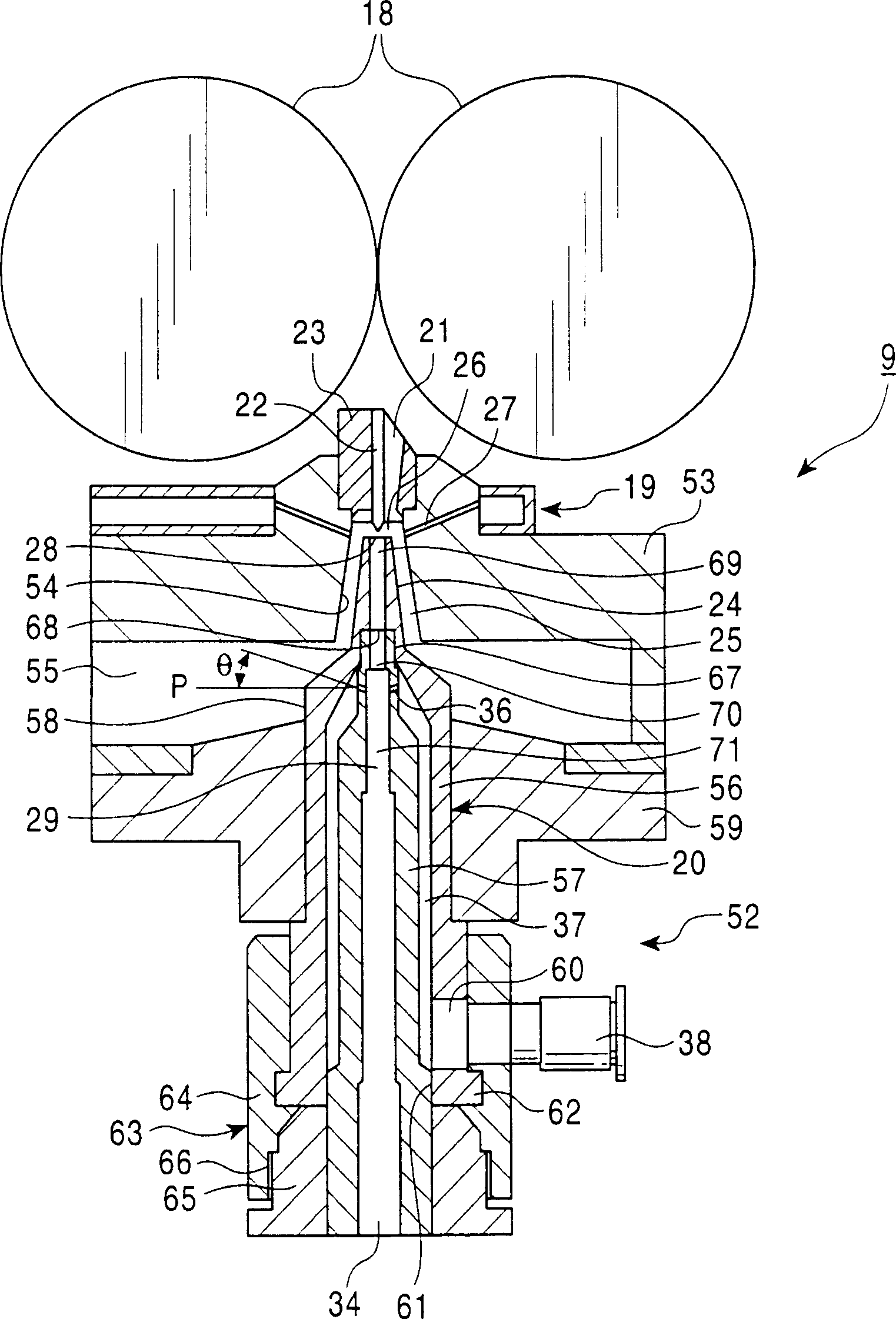
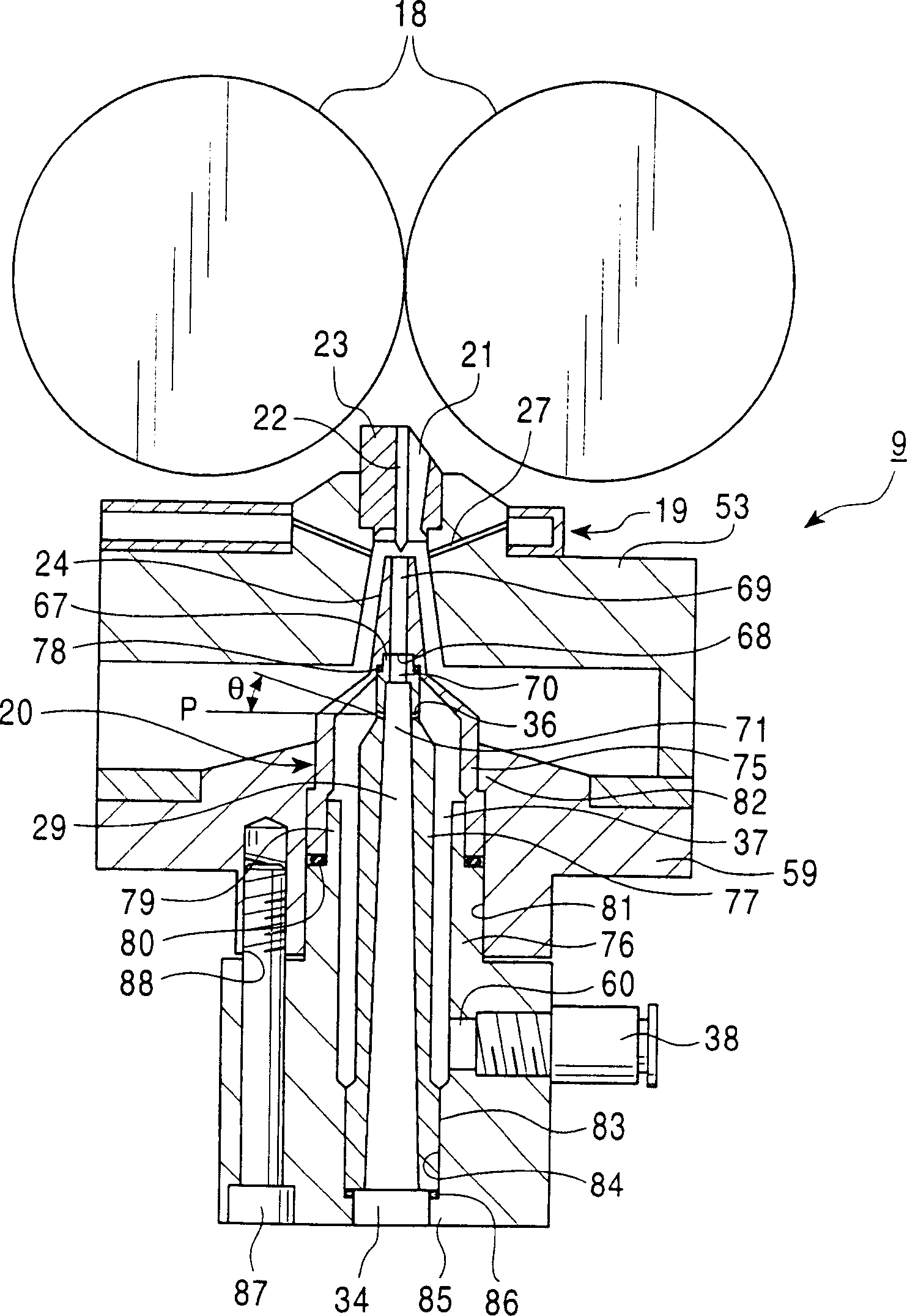
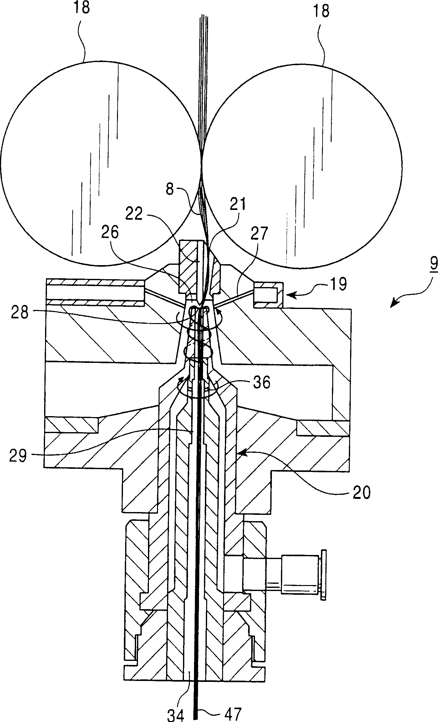
[0022] Such as Image 6 with Figure 7 As shown, each spinning component 2 is arranged on the casing 6 of the spinning machine 1 body, and the drafting device 7 arranged near the upper end of the casing 6 is arranged on the downstream side of the drafting device 7 and will be drawn from the drafting device 7. The spinning section 9 that spins the fiber bundle sent out by the device 7 into yarn, the yarn feeding device 11 that is installed on the downstream side of the spinning section 9 and conveys the spun yarn 10 discharged from the spinning secti...


PUM


Abstract

The invention provides a high-speed spinning by increasing success rates of the taking-out of a yarn and the piecing of the yarn. This spinning frame has a pneumatic spinning nozzle 27 for generating a rotational gas flow at the vicinity of a tip part 24 of a hollow guide shaft 20 and an assistant nozzle 36 for generating the rotational gas flow in a yarn passage 29 in a hollow guide shaft 20. The assistant nozzle 36 is tilted so as to be directed to the downstream side based on the plane P orthogonal to the yarn passage 29. The tilting angle of the assistant nozzle 36 is preferably 10-35 degrees, more preferably 20 degrees. As a result, the component of the flow directed to the downstream side, and accompanied by the rotational gas flow generated by the assistant nozzle is enlarged, and the sucking power into the yarn passage is enhanced. The balance between the components in the downstream direction and the rotational direction is corrected and the yarn strength of a bound yarn to be discharged is increased to prevent the yarn break or the like.

Description

technical field [0001] The present invention relates to a spinning device for producing a true twisted spun yarn by acting a swirling airflow on a fiber bundle. Background technique [0002] In a spinning device having a hollow yarn guide shaft (refer to Japanese Patent Laid-Open No. 2001-159033, etc.), around the front end of the hollow yarn guide shaft, compressed air (pressurized gas) jetted from an air spinning nozzle ) generates a swirling airflow, using the swirling airflow, the fiber bundle sent from the drafting device is separated into fibers, and the fibers are twisted in the swirling direction to become a real-twist yarn, and then passed through the hollow yarn guide shaft The yarn channel in the center of the body is continuously discharged, and then wound up on the package. In addition, when the spinning device is operated, or when the yarn is broken when the yarn is broken, the yarn passage formed in the hollow yarn guide shaft body, and in the tangential dire...

Claims


Application Information

Patent Timeline
Patent Type & Authority Applications(China)
IPC IPC(8): D01H1/115D01H4/02D01H4/48
CPCD01H4/02D01H4/48D01H1/115D01H15/002
Inventor 目片努
Owner MURATA MASCH LTD
Why Eureka
Try Eureka