Yarn tension constant compensation device

A compensating device, a technology for yarn tension, applied in textiles and papermaking, knitting, warp knitting, etc., can solve the problems of inability to achieve smooth, stable and continuous operation of equipment, long spring response time, strong yarn jitter, etc. Good shock absorption effect, high product quality, and the effect of reducing production costs

Pending Publication Date: 2017-10-24
JINJIANG PENGTAI MACHINERY TECH CO LTD
View PDF7 Cites 2 Cited by
  • Summary
  • Abstract
  • Description
  • Claims
  • Application Information

AI Technical Summary

Problems solved by technology

With this structure, the yarn guide rod vibrates strongly under the action of the spring, and the spring response time is long. The cockscomb sprocket is pulled by the spring and has a large inertia, resulting in strong yarn vibration and large jump, which may easily lead to yarn breakage, and cannot achieve smooth, stable and continuous The purpose of operating the equipment

Method used


Image

  • Yarn tension constant compensation device
  • Yarn tension constant compensation device
  • Yarn tension constant compensation device

Examples


Embodiment

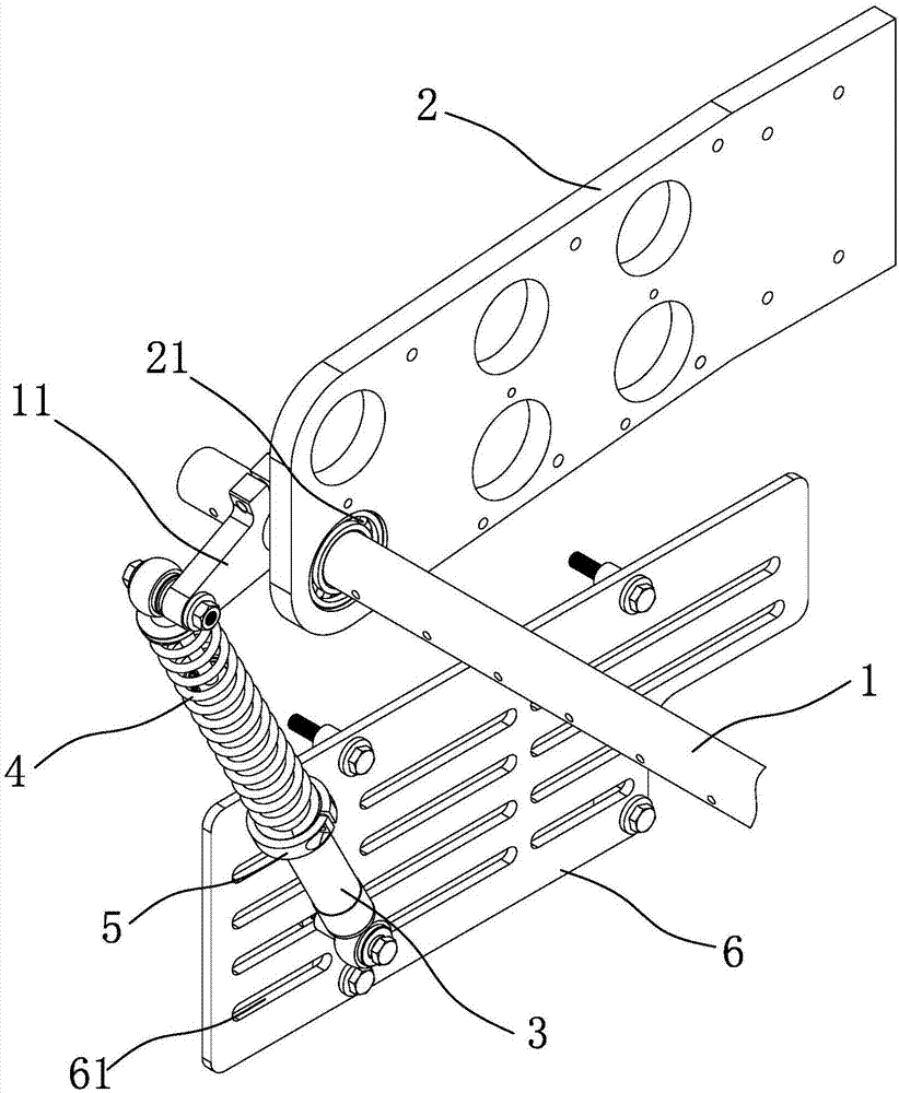
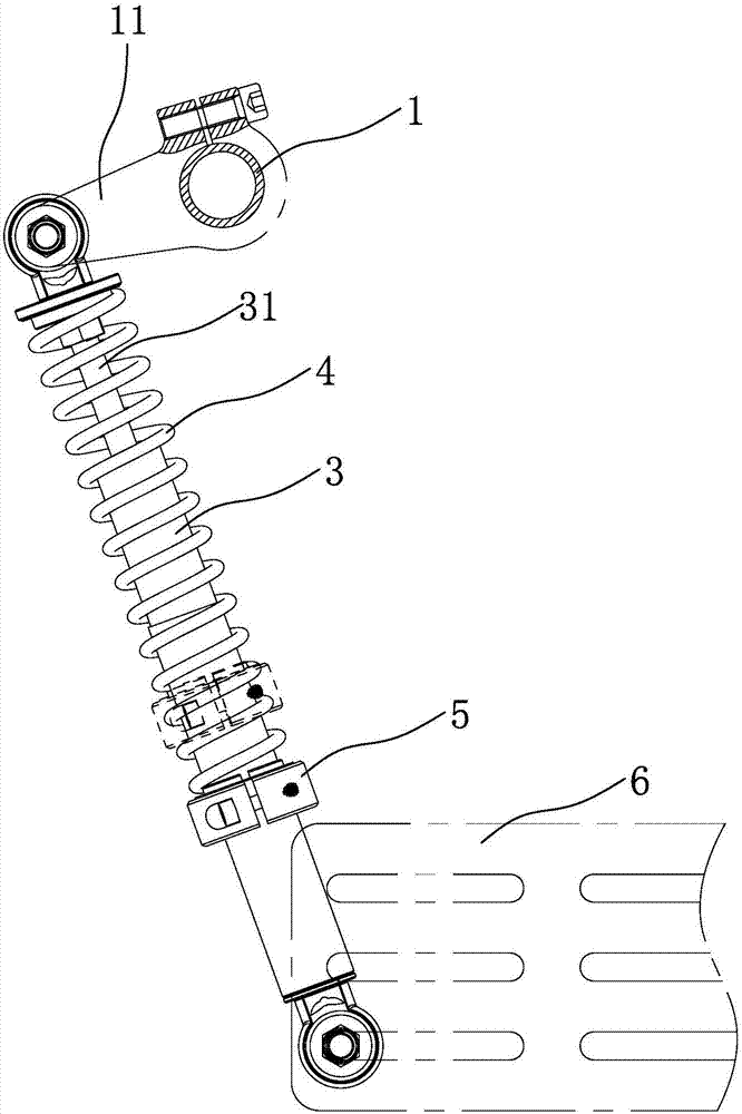
[0016] refer to figure 1 and figure 2 , a kind of yarn tension constant compensating device, comprises frame and six yarn guide rods 1 ( figure 1 Only one is shown as an example), the frame is provided with a support plate 2 with six mounting holes, and each yarn guide rod 1 is installed on the support plate 2 through self-aligning bearings 21;

[0017] Each yarn guide rod 1 is connected with a tension compensation mechanism, and the tension compensation mechanism includes a damping cylinder 3, a spring 4 sleeved on the outer surface of the damping cylinder 3, and a clamp ring 5, and one end of the damping cylinder 3 is fixed on the frame. On a mounting plate 6, the other end is connected to the yarn guide rod 1 through a connecting lever 11, the spring 4 is clamped between the end of one end of the damping cylinder 3 and the clamping ring 5, and the clamping ring 5 is connected to the damping Cylinder 3 threaded connection. In this embodiment, the outer surface of the cyl...


PUM


Abstract

The invention relates to a yarn tension constant compensation device. The device comprises a rack and multiple yarn guiding rods installed on the rack, a tension compensation mechanism is connected to each yarn guiding rod, each tension compensation mechanism comprises a damping cylinder, a spring arranged on the outer surface of the damping cylinder in a sleeving mode and a clamping ring, wherein one end of the damping cylinder is fixed to the rack, the other end of the damping cylinder is connected with the corresponding yarn guiding rod through a connecting plate, the spring is clamped between the end, connected to the connecting plate, of the damping cylinder and the clamping ring, the clamping ring is in threaded connection with the damping cylinder, a piston assembly inside the damping cylinder comprises a piston rod, a piston and a fixing part used for fixing the piston, the piston comprises a piston body and multiple piston sheets installed at the two ends of the piston body, the piston body is provided with multiple first oil channels and second oil channels which are cut through in the axial direction, and the first oil channels and the second oil channels are distributed at intervals in the circumference direction of the piston body. The yarn tension constant compensation device is applicable to damping and yarn-breaking-prevention of the yarn guiding rods on textile equipment.

Description

technical field [0001] The invention relates to the technical field of textile equipment, in particular to a yarn tension constant compensation device. Background technique [0002] Due to the special motion required for knitting and the special requirements for the quality of the cloth surface of the warp knitting machine, the yarn needs to maintain a constant tension so that the equipment can maintain stable operation. In the prior art, a spring is installed on the equipment, one end of the spring is fixed on the frame, and the middle is connected by a chain and a sprocket, and the sprocket is fixed on the yarn guide rod, and the yarn guide rod rotates, driving the sprocket to pull the spring back and forth to expand and contract. Shock absorption, such as the Chinese patent CN102108599B with the date of authorization announcement on May 02, 2012, discloses a warp knitting machine yarn tension control device, the yarn guide rod, tension rod and yarn guide cap supported by ...

Claims


Application Information

Patent Timeline
Patent Type & Authority Applications(China)
IPC IPC(8): D04B27/12D04B27/14
CPCD04B27/12D04B27/14
Inventor 王启超王启勇陈浩
Owner JINJIANG PENGTAI MACHINERY TECH CO LTD
Why Eureka
Try Eureka