Welding device and method

A welding equipment, welding point technology, applied in welding equipment, arc welding equipment, metal processing equipment, etc., can solve the problems of impracticality, dull work, waste of capacity, etc.

Inactive Publication Date: 2003-04-09
STX FINLAND OY
View PDF7 Cites 11 Cited by
  • Summary
  • Abstract
  • Description
  • Claims
  • Application Information

AI Technical Summary

Problems solved by technology

Also, for relatively simple welding, the use of skilled welders wastes their abilities and is not only tedious but also impractical

Method used


Image

  • Welding device and method
  • Welding device and method
  • Welding device and method

Examples


Embodiment Construction

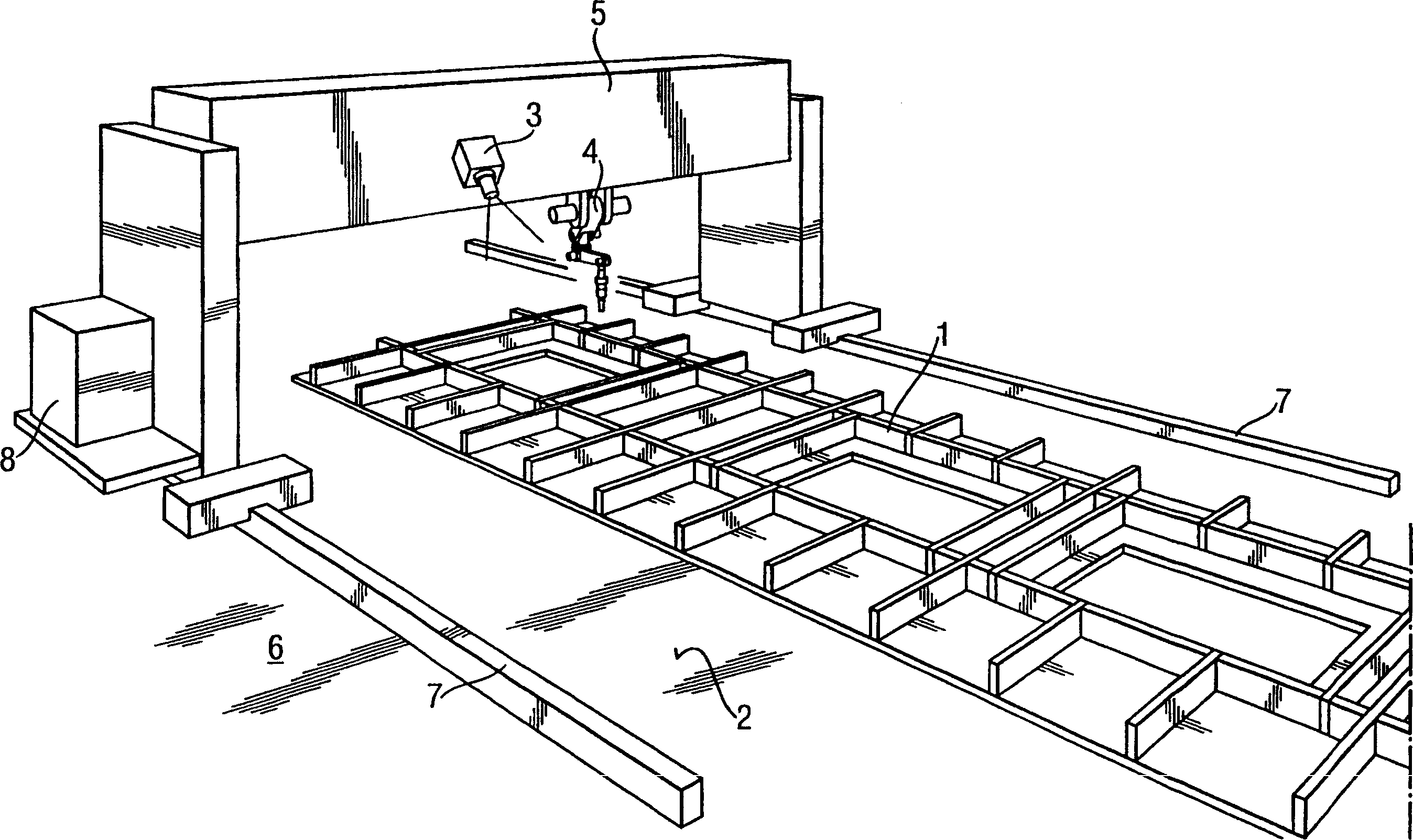
[0024] figure 1 A welding station or device is shown in which the individual components of a structural part 1 to be welded are supported on a support surface 2 . These components can be moved onto the support surface manually, by crane or by automatic material control. A camera 3 and a welding device 4 are fixed on a lateral support structure 5 which straddles the support surface 2 and which can be moved along the length of the support surface 2 via side rails 7 mounted on the ground 6 , the side rails are located on both sides of the supporting surface 2 respectively. A handling device 8 for handling the support structure 5 and / or the welding device 4 and / or the camera 3 is located close to the support structure 5 .

[0025] The term "camera" is intended to include any imaging device capable of providing an image of the structure to be welded, and may include conventional photographic devices such as a video camera or just a camera, imaging devices with infrared or ultravi...


PUM


Abstract

The forming process of welded structural member incldues supporting the constituent parts in prospective membrane shape and welding in several welding spots. The welding method includes at least one image of the part arranging positions on the support plane for determining the welding spot positions. The corresponding welding equipment is also disclosed.

Description

technical field [0001] The invention relates to a method for welding and forming a plurality of component parts into a welded structural part. The invention also relates to a forming device for welded structural parts. Background technique [0002] Welding operations for conventional low-batch welded structures are usually mostly performed by hand. This is because it is neither scientific nor economical to weld the main parts of most components with current automatic welding devices. For welding in small batches, existing welding devices are only suitable for those easily accessible, long and straight weldments. But the welding of most weldments is used to join relatively short and intersecting structural members, and its accessibility is limited by the surrounding structural members. This poses a particular problem in the shipbuilding industry, where weldments are larger in size and number. Such components are manually welded, which is expensive and time-consuming. [...

Claims


Application Information

Patent Timeline
Patent Type & Authority Applications(China)
IPC IPC(8): B23K9/00
Inventor M·维科莱宁J·赛科
Owner STX FINLAND OY
Why Eureka
Try Eureka