
Wave guide twist

A technology of waveguide and rectangular waveguide, which is applied in the direction of waveguide devices, circuits, electrical components, etc., can solve the problems of high cost

Inactive Publication Date: 2003-04-09
TELEFON AB LM ERICSSON (PUBL)
View PDF1 Cites 6 Cited by
  • Summary
  • Abstract
  • Description
  • Claims
  • Application Information

AI Technical Summary

Problems solved by technology

This structure is expensive and only suitable for the coupling of waveguides with coincident cores

Method used


Image

  • Wave guide twist
  • Wave guide twist
  • Wave guide twist

Examples


Embodiment Construction

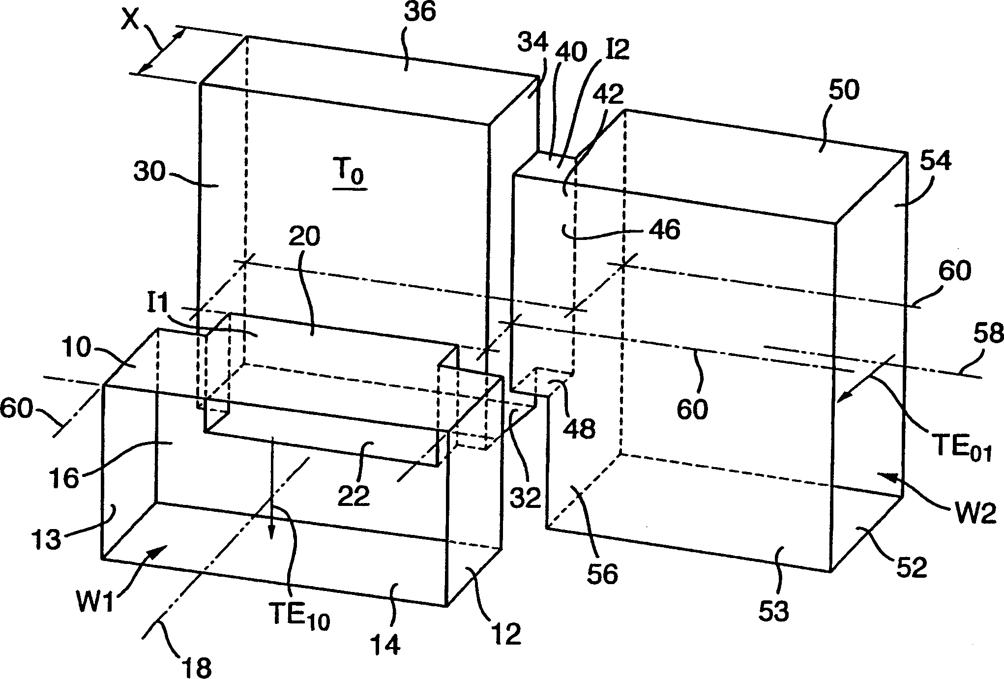
[0011] figure 1 is a schematic isometric illustration of the inner wall of a torsional transformer structure fabricated from solid metal. For clarity, the exterior of the structure and connecting flanges etc. have been omitted.

[0012] The first port consists of a standard rectangular waveguide section W1 with long side walls 10 , 14 and short side walls 12 , 13 . The waveguide W1 passes through the first die I1 and the central dual-mode transformer part T 0 The front end face 30 is coupled. In this embodiment, the upper surface 20 of the die I1 constitutes an extension of the upper surface of the long side wall 10 of the waveguide W1. The lower surface 22 of the die I1 constitutes the transformer T 0 extension of the lower surface. The second port consists of a second standard rectangular waveguide part W2 with long sidewalls 50, 52 and short sidewalls 53, 54, the waveguide W2 passes through the second die I2 and the transformer part T 0 The sidewall 34 is coupled. In...


PUM


Abstract

In a waveguide twist which provides orthogonal rotation of both direction and polarization, TE10-mode energy in waveguide W1 is coupled via iris I1 to a transformer cavity capable of exciting both TE10 and TE01 modes. The TE01 mode is coupled via iris I2 to output waveguide W2. Transformers may be interposed between one or both waveguides and their associated irises to increase bandwidth. The configuration facilitates manufacture in two halves by simple machining or casting.

Description

technical field [0001] The present invention relates to transitions between two orthogonally arranged rectangular waveguide ports, and more particularly to such transitions in which the orientation of the waveguide sections is also orthogonal. This transition is especially applicable to integrated waveguide subsystems. Background technique [0002] Waveguide twists are known for allowing coupling between waveguides with different angular orientations. One of these types using progressive twisting sections is discussed by Wheeler H.A. in "Step-Twist Waveguide Components" in IRE Trans. Microwave Theory Tech. (Vol. MTT-SPP. 44-52), October 1955. kind. This transition utilizes the middle sections of rectangular waveguides connected in series and arranged at progressively increasing tilt angles. This structure is expensive and is only suitable for the coupling of waveguides with coincident axes. Another waveguide twist for coupling between waveguides whose axes are parallel b...

Claims


Application Information

Patent Timeline
IPC IPC(8): H01P1/02H01P1/161
CPCH01P1/02H01P1/161
Inventor U·罗森贝格K·贝斯
Owner TELEFON AB LM ERICSSON (PUBL)
Learn More