Resistor banks

A technology of resistance row and resistance element, applied in the direction of resistors, resistor parts, circuits, etc., can solve the problems such as the decline of the electrical insulation performance of the spacer and the intrusion of pollution.

Inactive Publication Date: 2003-04-09
CRESSALL RESISTORS
View PDF0 Cites 6 Cited by
  • Summary
  • Abstract
  • Description
  • Claims
  • Application Information

AI Technical Summary

Problems solved by technology

These cracks are susceptible to the invasion of pollution, and the presence of pollution will lead to a decrease in the electrical insulation performance of the spacer

Method used


Image

  • Resistor banks
  • Resistor banks
  • Resistor banks

Examples


Embodiment Construction

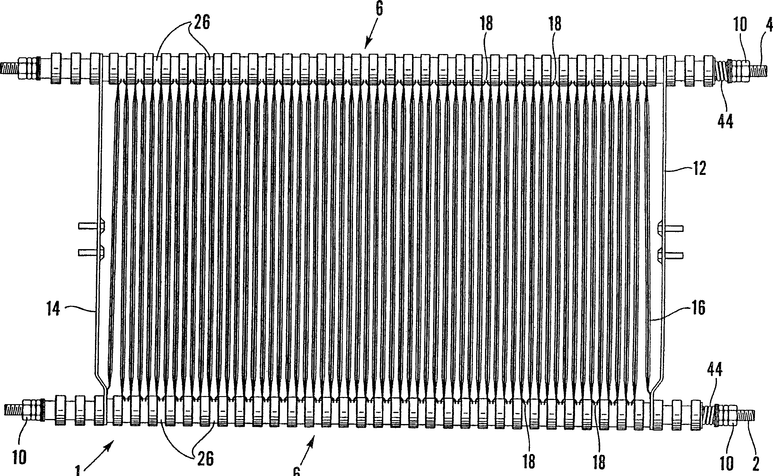
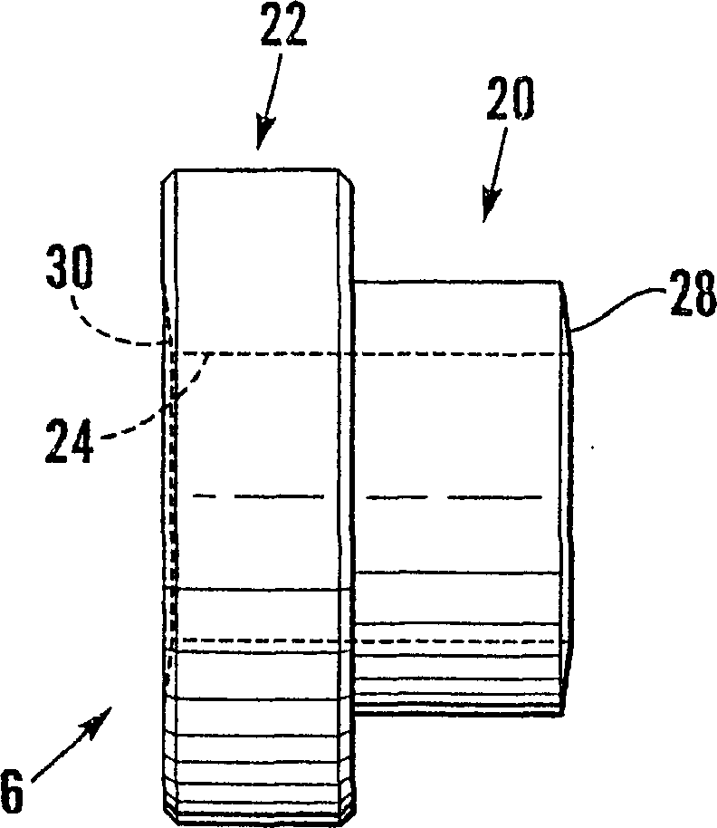
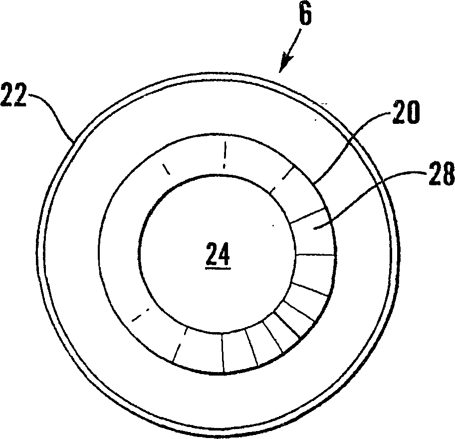
[0027] see now figure 1 In the figure, a resistor row used in the traction vehicle electric brake resistor system is generally represented by number 1. The resistance bar 1 comprises first and second support members 2, 4 in the form of cylindrical steel rods commonly called tie rods. On each support member 2, 4 or support member 1, 4 is a thin tube of silicone bonded mica (not shown) which provides insulation. Installed on the mica tube of each bar 2,4 are a plurality of insulating spacers 6 made of ceramic material, each spacer has the shape of a "top hat", that is to say, each spacer 6 includes two Cylindrical parts 20, 22 of different diameters (see Figure 2A and 2B). Each spacer 6 has a centrally located rod receiving hole 24 of a diameter slightly larger than that of the rods 2,4 on which the spacer 6 is slidably received. The spacers 6 are mounted end-to-end so that the large-diameter cylindrical portion 22 of one spacer 6 abuts the small-diameter cylindrical porti...


PUM


Abstract

A resistor bank has first and second supporting members (2, 4). Held on to the supporting members (2, 4) is a resistor element (16) comprising a strip of resistor material which is bent into a zigzag shape. The strip (16) is continuous and has a non-planar cross sectional profile. A plurality of insulating spacers (6) mounted end to end on each of the first and second supporting members (2, 4) isolate the element (16) from the first and second supporting members (2, 4). The engaging surfaces of adjacent spacers (6) are of a complimentary shape thereby to enable each spacer (6) to move relative to each adjacent spacer (6) with any flexing of the relevant one of the supporting members (2, 4). The element (16) is held by a plurality of clips (26) each at a bend thereof on to a respective one of the supporting members (2, 4). Each clip (26) has at least one fastening lug for insertion into at least one fastening hole in a corresponding bend in the element (16).

Description

technical field [0001] The invention relates to a resistor bank of the type used in an electric braking resistor system of a traction vehicle. Background technique [0002] Electric motor-driven traction vehicles, such as trains, trams, etc., mostly use two types of braking devices, one is a friction braking device, which consists of friction blocks or pads applied to the vehicle or axle, for example by compressed air or hydraulic transmission The other is an electric braking device, which includes a resistor system that is applied to the traction motor in the form of an electrical load, thereby retarding its rotation. [0003] The electric braking resistor system includes resistor banks, each resistor bank having a pair of support members between which the resistor element is clamped. The resistive element can consist of several parts which can be joined together by soldering and bent to create a zigzag shape. The bent resistive element is clamped to the support member by...

Claims


Application Information

Patent Timeline
Patent Type & Authority Applications(China)
IPC IPC(8): B60T10/00H01C1/014H01C3/10
CPCB60T10/00H01C3/10H01C1/014
Inventor A·J·埃弗里特
Owner CRESSALL RESISTORS
Why Eureka
Try Eureka