Bait-feeding type reel

A technology of reel and fishing line, applied in the direction of fishing reel, fishing, application, etc., can solve the problems of increased production cost and the like

Inactive Publication Date: 2003-04-23
SHIMANO INC
View PDF1 Cites 8 Cited by
  • Summary
  • Abstract
  • Description
  • Claims
  • Application Information

AI Technical Summary

Problems solved by technology

Therefore, the productio

Method used


Image

  • Bait-feeding type reel
  • Bait-feeding type reel
  • Bait-feeding type reel

Examples


no. 1 example

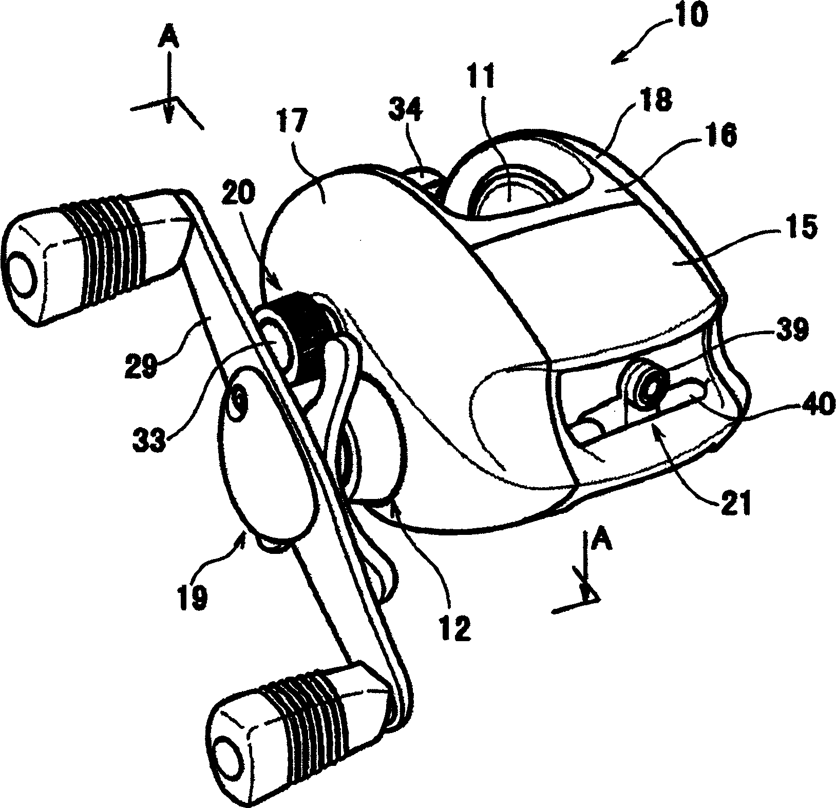
[0035] figure 1 It is a perspective view of the bait-casting reel 10 according to the first embodiment of the present invention.

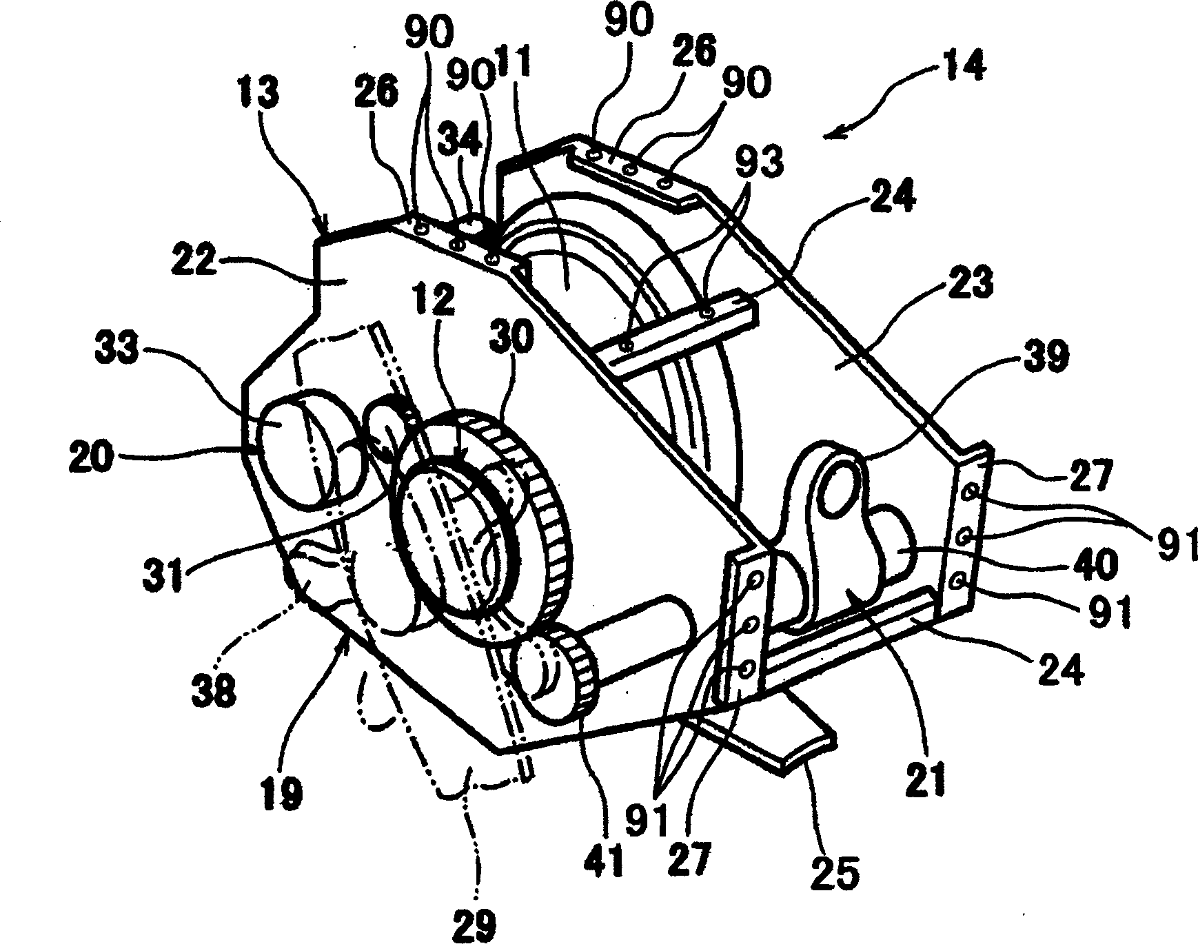
[0036] see figure 1 , the bait-casting reel 10 includes a connector 13 (see figure 2 ) in a reel 11 and a reel driving mechanism 19 that drives the reel 11. The spool 11 and the spool drive mechanism 19 are essential functional parts of the bait casting reel 10 . Thus, a base unit 14 having all the essential functions of the bait casting reel 10 is constructed. Then, the outer panels 15 - 18 serving as the surfaces of the baitcasting reel 10 are attached to the base unit 14 . This results in a baitcasting reel of superior design.

[0037] In other words, the first to fourth outer panel members 15 - 18 described below are used only to form the appearance of the bait casting reel 10 . In this way, the basic functional design of the baitcasting reel 10 can be simplified. At the same time, the exterior design of the bait-casting reel 10 can ach...

no. 3 example

[0073] Combine below Figure 8-11 The second and third embodiments of the present invention will be described. Figure 8 and10 The baitcasting reel 60 of the second embodiment is shown, while Figure 9 and 11 A bait reel 61 of a third embodiment is shown.

[0074] Figure 8 and 9 are perspective views of bait casting reels 60 and 61 according to second and third embodiments of the present invention, respectively.

[0075] As in the first embodiment described above, in this embodiment, each of the bait-casting reels 60 and 61 has a base unit and an outer plate connected to the base unit. The basic unit and the outer panels will be described below. In other words, the bait-casting reels 60 and 61 have a common base unit 62 having all the requisite functions of the bait-casting reels 60 and 61 . Thus, baitcasting reels 60 and 61 function the same, but differ in appearance. In the following description, the same components as those of the above-mentioned bait casting reel ...


PUM


Abstract

The bait casting reel includes a basic unit that includes a spool, a spool driving mechanism, and an attachment frame, and outer plate members that are attached to the attachment frame. All the functional members are installed in the attachment frame, such that the basic unit can perform all the indispensable functions of the bait casting reel. The outer plate members are attached to the attachment frame such that the outer plate members form the surface of the bait casting reel. The present invention allows easy and more flexible ornamental design of bait casting reel while securing its indispensable functions. The present invention also provides a common part of a bait casting reel, which can be used in bait casting reels of other models.

Description

technical field [0001] This invention relates generally to dual bearing reels, and more particularly to so-called baitcasting reels for casting bait. Background technique [0002] The so-called bait-casting reel generally includes a reel main body that can freely release and reel the fishing line and a crank that implements the operation of reeling the fishing line. [0003] The reel main body includes a main frame, a reel for winding the fishing line, a reel drive mechanism for rotating the reel, a drag mechanism for limiting the reel to finish the fishing line and a reel for winding the fishing line are installed in the main frame. A horizontal winding mechanism that evenly winds the fishing line on the reel when fishing the line. The reel driving mechanism is formed so that a crank can be connected thereto. To facilitate manipulation of the crank, the crank is located at a location extending outwardly from the reel body. [0004] In the existing bait-casting type reel,...

Claims


Application Information

Patent Timeline
IPC IPC(8): A01K89/015A01K89/033
CPCA01K89/015A01K89/0155A01K89/0186A01K89/01912A01K89/0192
Inventor 明上诚治
Owner SHIMANO INC
Why Eureka
Try Eureka