
Fetch channel device and its method

A channel device and sampling device technology, applied in the field of optical storage systems, can solve the problems of delay time reducing the performance of high-speed optical storage systems, etc.

Inactive Publication Date: 2003-04-23
MEDIATEK INC
View PDF2 Cites 2 Cited by
  • Summary
  • Abstract
  • Description
  • Claims
  • Application Information

AI Technical Summary

Problems solved by technology

Although this patent pending greatly reduces the sampling frequency, the delay time due to the upsampler reduces the performance of high-speed optical storage systems

Method used


Image

  • Fetch channel device and its method
  • Fetch channel device and its method
  • Fetch channel device and its method

Examples


Embodiment Construction

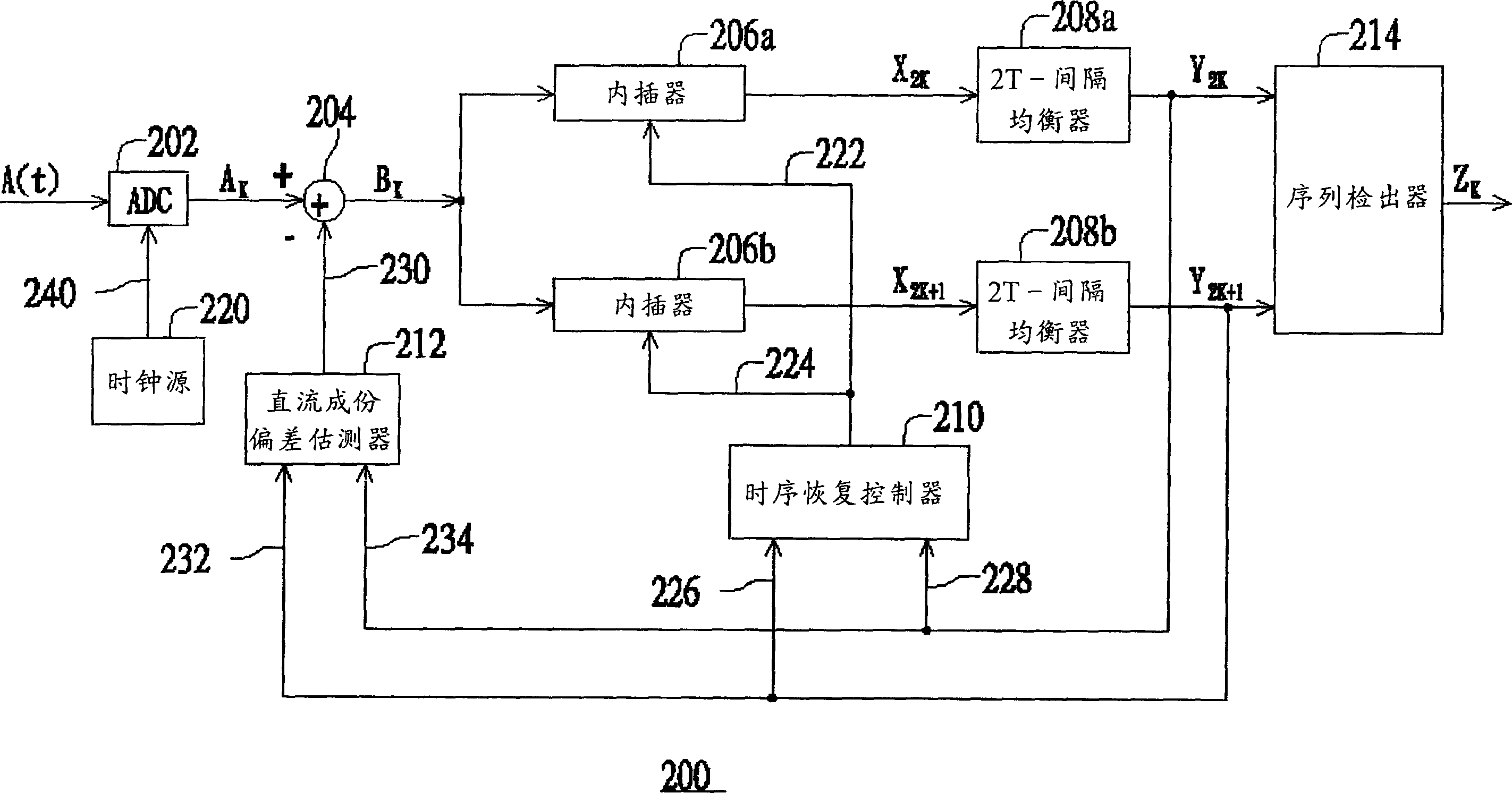
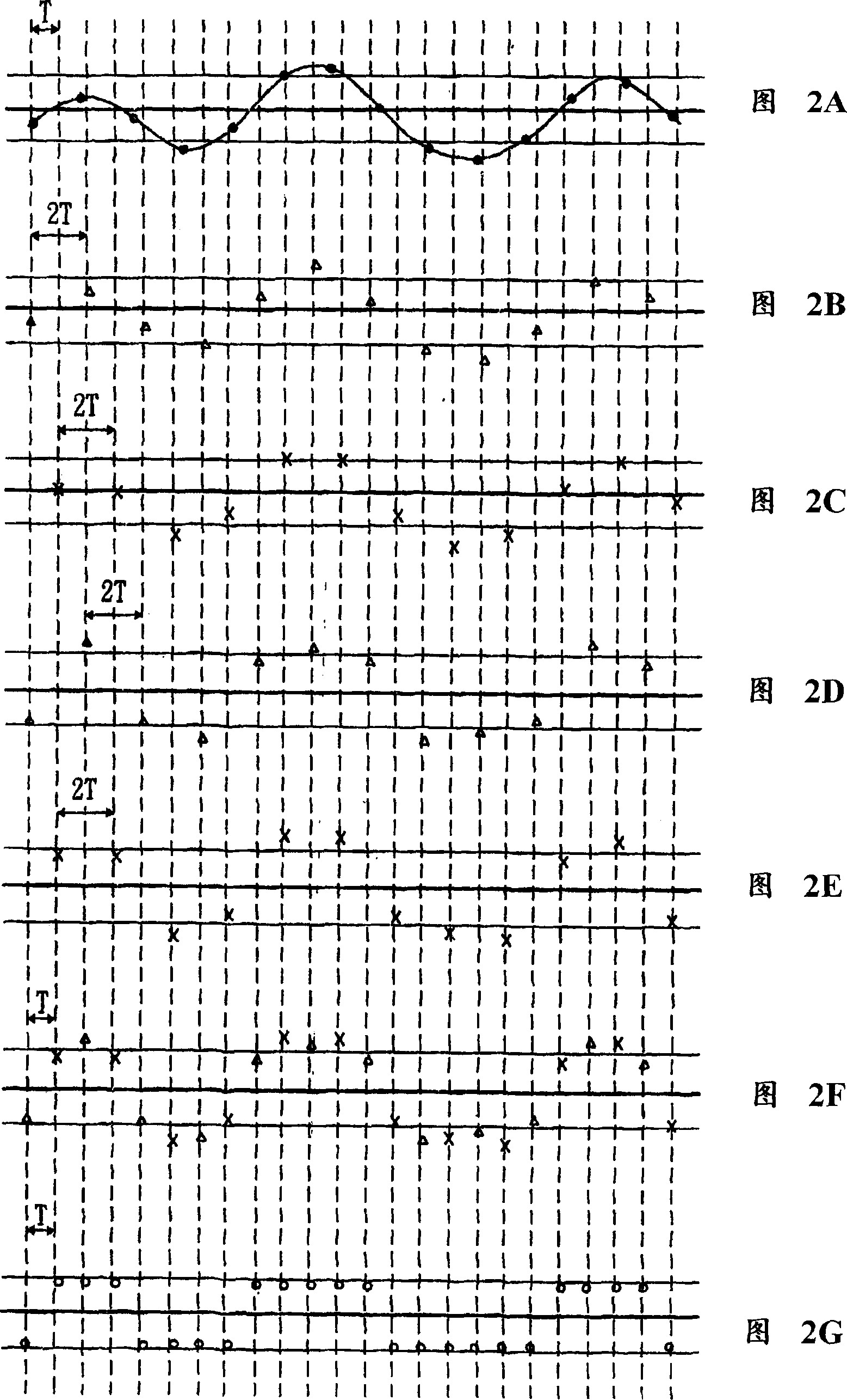
[0018] refer to figure 1 Features of the present invention will become more apparent with reference to FIGS. 2A-2G and the following detailed description. Such as figure 1 As shown, the read channel device 200 is suitable for reading data recorded in an optical storage system at a predetermined baud rate. The analog read signal A(t) generated from the optical storage system is asynchronously sampled by the sampling device 202 (that is, the analog-to-digital converter ADC) to generate a sequence of asynchronous sampling values ​​A K . The sampling device 202 operates according to a clock with a fixed frequency fs, which is the sampling clock 240 provided by the clock source 220 . Asynchronously sampled values ​​of the sequence A K The relationship with the analog read signal A(t) can be expressed as

[0019] A K ={. . . , A(0), A(τ), A(2τ), . . . , A(kτ), . . .} where k is an integer and τ=1 / fs. In Figure 2A, the analog read signal A(t) is represented by a solid line and...


PUM


Abstract

The fetch channel device for fetching data recorded on the optical storage system according to defined baud rate is characterized by that said device can nonsynchronously sample analog fetch signal from optical storage system and substract an estimation-measured D.C. component deviation value from nonsynchronous sample value to obtain a sequential nonsynchronous D.C. component removed sampling value, said sampling value is respectively interpolated by two interpolars to respectively produce a sequential synchronous even-time sampling value and a sequential synchronous odd-time sampling value,then these sampling values are respectively equalized by two equalizes according to an object spectrum to respectively produce a sequential even-time equalization sampling value and a sequential odd-time equalization sampling value.

Description

technical field [0001] The invention relates to an optical storage system, in particular to a reading channel device and method suitable for the optical storage system. Background technique [0002] In recent years, the development of new optical recording media and data compression technology has made it possible to use optical storage systems to obtain huge data capacities. Optical storage systems can be used to store audio information, such as music CD players (CD players), as well as video and computer information, such as CD-ROMs and, more recently, DVD players. ). Information is usually recorded in binary form representing "0" and "1" bits by writing a series of "pits" onto optical media. When reading the data recorded on the optical media, an optical pick-up head on the rotating optical disc will detect the change of reflected light and generate an analog read signal. The analog read signal is then detected and decoded by a read channel circ...

Claims


Application Information

Patent Timeline
IPC IPC(8): G11B5/09G11B7/005G11B20/10H03H7/30
Inventor 黄克强王梓百
Owner MEDIATEK INC
Learn More