Method and circuit for sampling data

A data and circuit technology, applied in the field of data recovery circuits, can solve the problems of increasing the design difficulty of clock and data recovery circuits 100

Inactive Publication Date: 2007-10-31
SILICON INTEGRATED SYSTEMS
View PDF0 Cites 3 Cited by
  • Summary
  • Abstract
  • Description
  • Claims
  • Application Information

AI Technical Summary

Problems solved by technology

Then, another disadvantage is that in the aforementioned structure, the clock frequency must be maintained at a very high operating frequency, so as to be able to match the input data D in high data frequency; this means that the system must build a controllable oscillator (such as a voltage-controll

Method used


Image

  • Method and circuit for sampling data
  • Method and circuit for sampling data
  • Method and circuit for sampling data

Examples


Example Embodiment

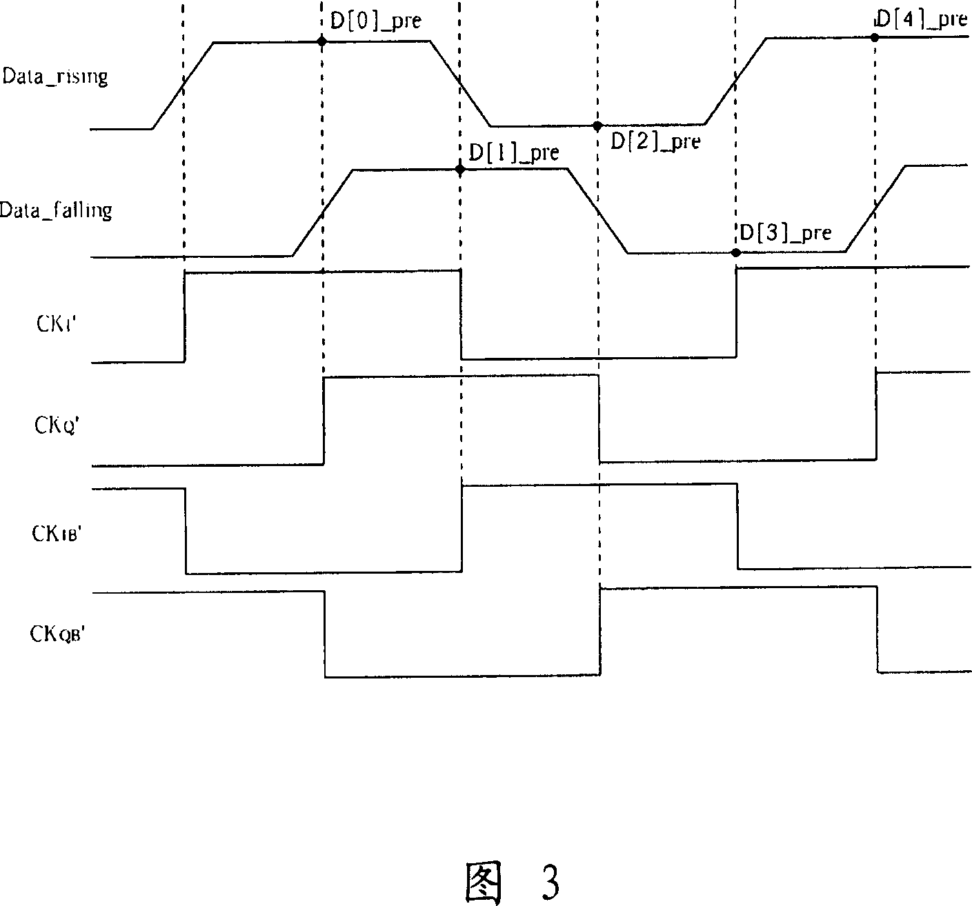
[0019] Please refer to FIG. 3 . FIG. 3 is a schematic diagram illustrating the clock and data recovery of the present invention. In this embodiment, all recovered clocks CK I ’, CK Q ’, CK IB ’, CK QB 'Used to detect the recovery clock CK I ’, CK Q ’, CK IB 、CK QB ' and the phase relationship between the first adjusted data Data_rising and the second adjusted data Data_falling. where the recovered clock CK I ’ with CK IB 'Used to detect the phase error of the first adjusted data Data_rising, and recover the clock CK Q ’ with CK QB ' is used to detect the phase error of the second adjusted data Data_falling. In addition, all recovered clock CK I ’, CK Q ’, CK IB 、CK QB ’ are used for data recovery operations to generate recovery data D out'. In short, compared with the prior art, which only uses part of the recovered clock, the present invention utilizes the recovered clock more efficiently. In addition, in this embodiment, the first adjusted data Data_rising ...


PUM


Abstract

The invention provides a sampling data method. The method includes: providing a first data and a second data; providing a first clock and a second clock. Using the first clock detects the phase of the first data, using the first clock samples the second data. Using the second clock detects the phase of the second data, and using the second clock samples the first data.

Description

technical field [0001] The present invention relates to a clock and data recovery circuit, in particular to a data recovery circuit which can use an input data frequency divider to divide the frequency of input data to reduce the frequency of the required clock and its related method. Background technique [0002] Generally, the data stream received by the receiver is not synchronous; therefore, for subsequent data processing, timing information, such as a clock, must be extracted from the data to allow its The subsequent synchronous operation; in addition, the timing of the data must be readjusted (data retiming) to remove the jitter accumulated in the transmission. Therefore, the aforementioned clock extraction and data timing adjustment are called "clock and data recovery". However, clock and data recovery circuits must meet strict specifications defined by relevant receiver standards, which poses a major challenge in system and circuit design. [0003] Clock and data r...

Claims


Application Information

Patent Timeline
IPC IPC(8): H03L7/00H03L7/08H03L7/18
Inventor 李鐏镮黄蓝蓝
Owner SILICON INTEGRATED SYSTEMS
Why Eureka
Try Eureka