Aligner for ophthalmology apparatus

An alignment system, ophthalmology technology, applied in the field of alignment system, can solve the problems of additional weight and cost

Inactive Publication Date: 2003-08-06
REICHERT
View PDF2 Cites 7 Cited by
  • Summary
  • Abstract
  • Description
  • Claims
  • Application Information

AI Technical Summary

Problems solved by technology

This approach requires additional mea

Method used


Image

  • Aligner for ophthalmology apparatus
  • Aligner for ophthalmology apparatus
  • Aligner for ophthalmology apparatus

Examples


Embodiment Construction

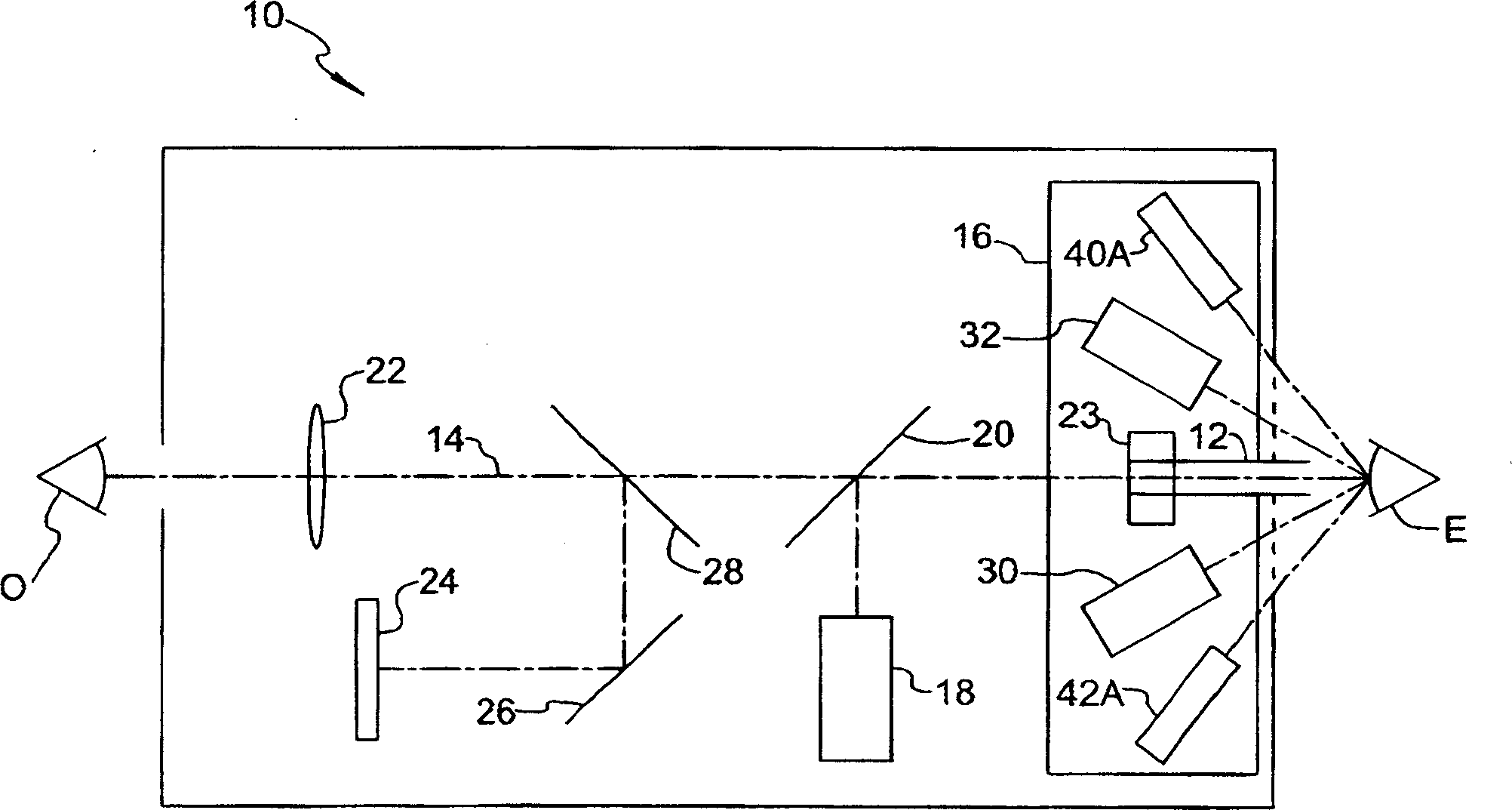
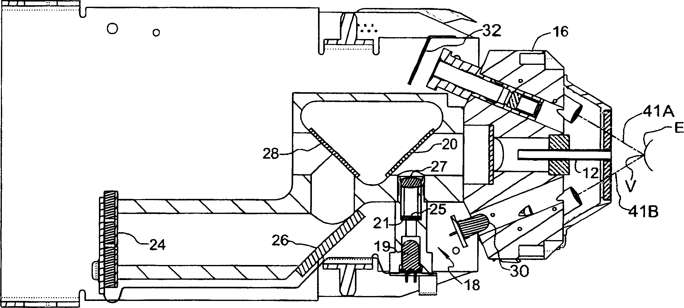
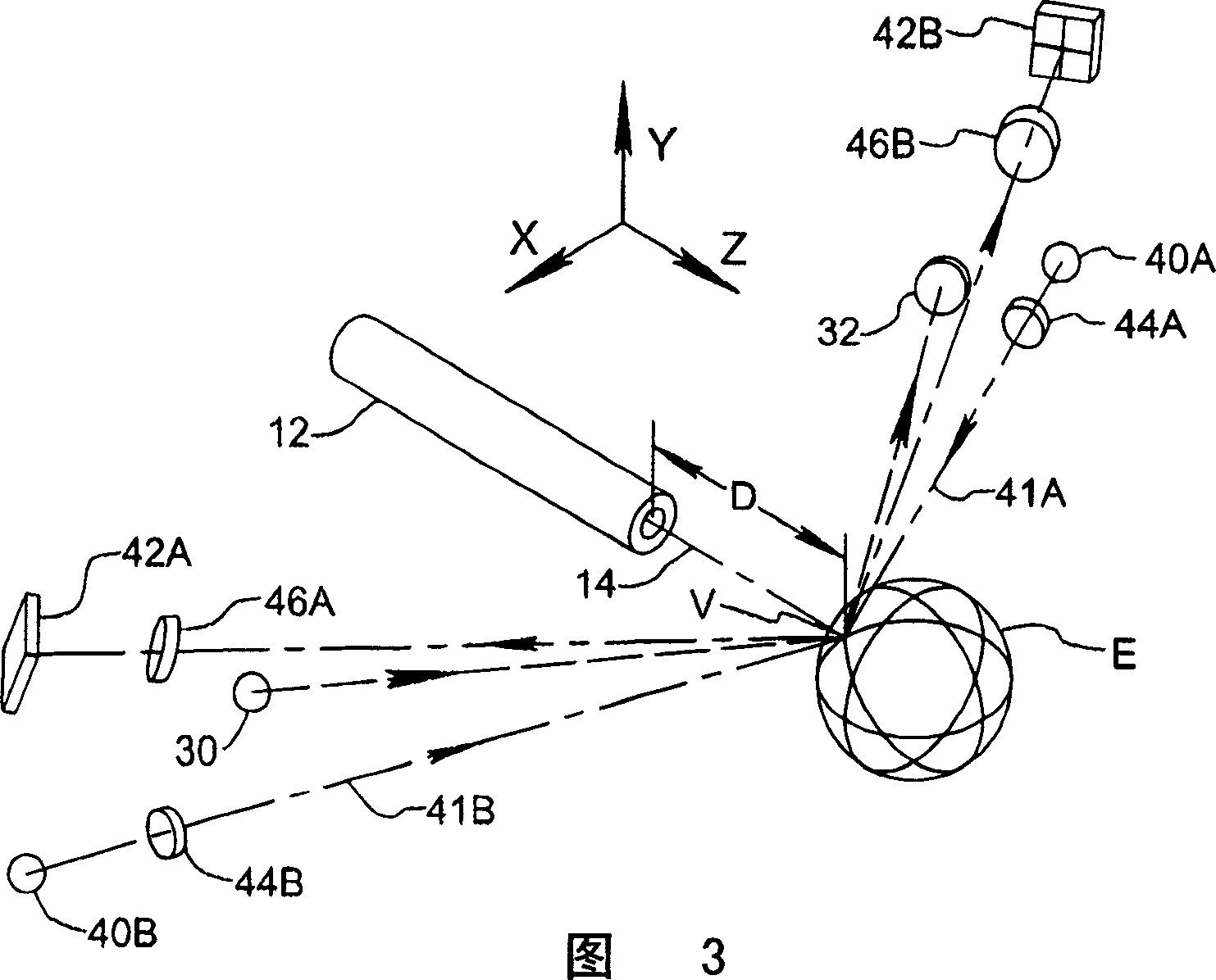
[0024] exist figure 1 In , an ophthalmic device incorporating the alignment system of the present invention is schematically shown and identified by the numeral 10 . Apparatus 10 is a non-contact tonometer operative for the purpose of discharging pulses of fluid through fluid discharge tube 12 to cause observable deformation of the patient's cornea for the purpose of measuring intraocular pressure. However, the invention may be practiced with other types of ophthalmic devices in which it is necessary to determine the X-Y or X-Y-Z alignment of the device relative to the eye.

[0025] Apparatus 10 includes an optical axis 14 aligned along its discharge tube 12; a nosepiece 16 secured near the front portion of the apparatus to facilitate mounting of the various optical and optoelectronic units of the apparatus as described below; a fixed object projection system 18, cooperating with the beam splitter 20 to present a visual fixed object to the patient along the optical axis 14; ...


PUM


Abstract

An alignment system for an ophthalmic instrument comprises an optical axis along which an operator can directly view the patient's eye and the patient can fixate on a dark fixation target surrounded by a bright background that helps to illuminate the eye for operator viewing. A position detection system utilizing stored geometrical relationships determined by multiple regression during instrument calibration compu tes X-Y-Z alignment status of the instrument relative to a patient's eye based on local x -y position information from a pair of lateral detectors receiving corneally reflected light from a corresponding pair of lateral light sources. A heads -up display im age is provided along an optical axis of the instrument for supplying instructive cues to an operator for moving the instrument to achieve alignment based on signal information from the position detection system, whereby the operator sees both a direct mac ro-image of the patient's eye and the display image. The alignment system is particularly suitable for use in hand-held ophthalmic instruments.

Description

field of invention [0001] The present invention relates generally to alignment systems for enabling an operator to position an ophthalmic device relative to a patient's eye, and more particularly to an alignment system suitable for use in a hand-held ophthalmic device as a positioning aid to provide the operator with a view of the patient's eye. Alignment system for direct observation. Background of the invention [0002] Alignment systems for use by an operator in positioning an ophthalmic device relative to a patient's eye vary in complexity. In devices where alignment is critical to measurement accuracy, such as in non-contact tonometers, means are provided for projecting a visually fixed target image along the device's measurement axis to guide the patient's line of sight and further provide the ability to sense the relative A photoelectric position detection system based on the position of the eye is common. Where the ophthalmic device is a non-contact tonometer with ...

Claims


Application Information

Patent Timeline
IPC IPC(8): A61B3/10A61B3/113A61B3/12A61B3/16
CPCA61B3/165A61B3/1208A61B3/113
Inventor C·珀西瓦D·H·胡维
Owner REICHERT
Why Eureka
Try Eureka