Pivoting fluid conduit joint and one-way brake

A technology of fluid pipelines and brakes, applied in the direction of pipes/pipe joints/fittings, adjustable connections, passing components, etc., can solve problems such as problems

Inactive Publication Date: 2003-08-20
TASK FORCE TIPS
View PDF2 Cites 5 Cited by
  • Summary
  • Abstract
  • Description
  • Claims
  • Application Information

AI Technical Summary

Problems solved by technology

Therefore, the swivel joint located on the outlet of the safety device is also problematic

Method used


Image

  • Pivoting fluid conduit joint and one-way brake
  • Pivoting fluid conduit joint and one-way brake
  • Pivoting fluid conduit joint and one-way brake

Examples


Embodiment Construction

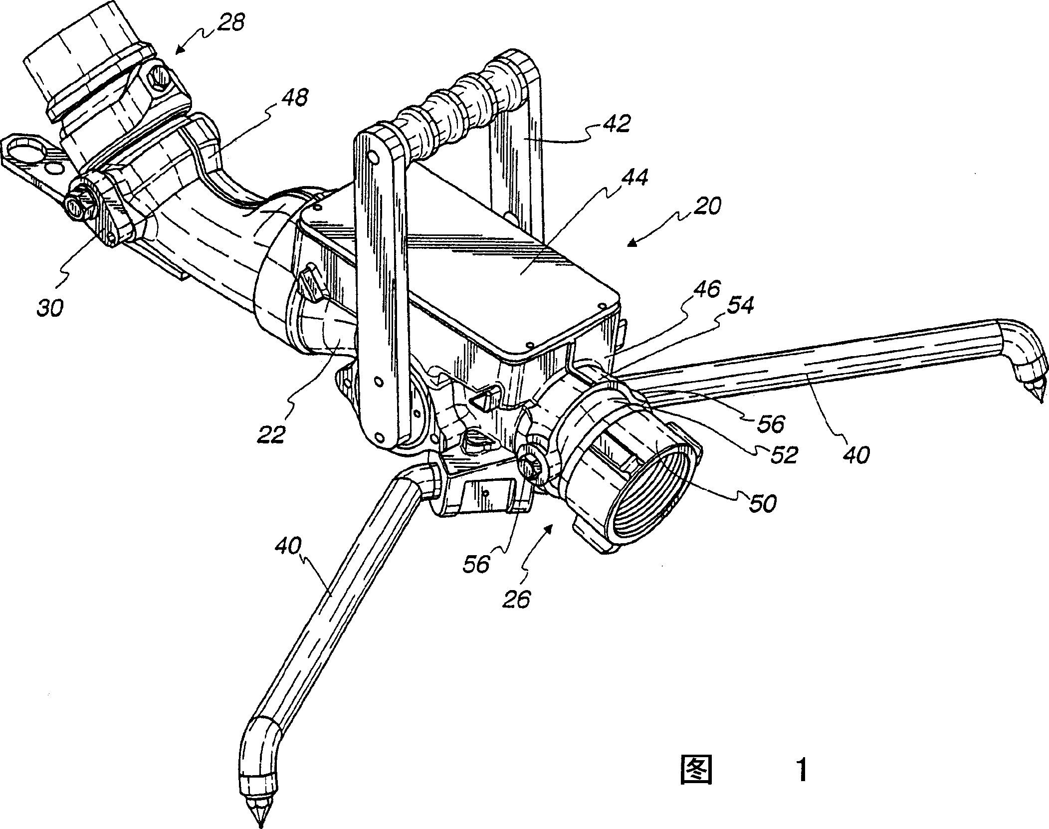
[0023] In the following description of the drawings, like elements are denoted by like numerals in each drawing. Generally speaking, in FIG. 1 , the safety device 20 has a housing 22 , a pivotable inlet connection 26 , a pivotable outlet connection 28 and a one-way stop 30 . Safety device housing 22 is shown as a rigid tube with spike-like folded legs 40 , a valve handle 42 and emergency valve shut-off mechanism 44 . The folding legs 40 are provided with a wide base on which the reaction forces of the safety device 20 can be supported and thus have a stabilizing effect. The valve handle 42 allows easy operation and is directly controlled by the operator. When the situation of sliding or overturning occurs, these situations will cause the next operation of the safety device 20 to be unsafe, and the emergency valve cut-off mechanism 44 can automatically cut off the safety device. Although safety device 20 is shown as a preferred shape and form of safety device for reasons of l...


PUM


Abstract

A pivoting joint (26) with a ball and socket joined by trunnions (56) for use in fluid conduits, particularly firefighting devices such as portable monitors and the like. The pivoting joint can be used on an inlet of the device to provide a pivoting motion for one or more inlet hoses, and / or on the outlet of the device to direct the discharge in one or more directions. An optional one-way brake (3d) can be used to limit unintended movement about one or more axis of motion.

Description

technical field [0001] This invention relates generally to pipe swivel joints, and more particularly to ball and socket pivotable joints for use in pipelines requiring the joint to rotate under pressure. A one-way stop can be mounted on the pivotable joint so that the pivotable joint can carry a heavy nozzle so that the height of the nozzle does not decrease due to gravity. Background technique [0002] A fire safety monitor is a device used to deliver large quantities of fire extinguishing fluid such as water or foam. The safety device has an inlet connected to a feed hose or pipe and a discharge fitted with a nozzle. Means are provided to change the direction of the nozzles so that the extinguishing fluid can move both horizontally and vertically. [0003] Some existing safety devices use ball and socket swivel joints to achieve horizontal and vertical movement. For example, a ball-and-socket rotary joint has fewer parts than a rotary joint using ball bearings, and is e...

Claims


Application Information

Patent Timeline
Patent Type & Authority Applications(China)
IPC IPC(8): B05B15/68A62C31/24F16L27/02F16L27/08
CPCA62C31/24F16L27/023F16L27/08F16L27/02
Inventor D·J·科拉奇R·麦克R·W·斯泰因加斯B·M·泰利斯
Owner TASK FORCE TIPS
Why Eureka
Try Eureka